Extensible 3D (X3D)
Part 1: Architecture and base components
11 Rendering component
 11.1 Introduction
The name of this component is "Rendering". This name shall be used when referring to this component in the COMPONENT statement (see 7.2.5.4 Component statement).
This clause describes the Rendering component of this part of ISO/IEC 19775. This includes fundamental rendering primitives such as TriangleSet and PointSet nodes, and geometric properties nodes that define how coordinate indices, colors, normals and texture coordinates are specified. Table 11.1 provides links to the major topics in this clause.
|
11.2 ConceptsThe following nodes represent the fundamental visual objects common to polygonal rendering systems:
Most complex geometries, such as those found in the 13 Geometry3D component and 14 Geometry2D component, can be implemented as a combination of these nodes. The Rendering component provides these nodes as basic services for building arbitrary geometry types.
All of the rendering primitive nodes are descendants of the X3DGeometryNode type.
Several geometry nodes contain Coordinate, Color or ColorRGBA, Normal, and TextureCoordinate as geometric property node types. The geometric property node types are defined as individual node types so that instancing and sharing is possible between different geometry nodes. The TextureCoordinate node type is defined in 18 Texturing component.
Color in X3D is specified using the RGB color model in which the three components of color specifications are red, green, and blue ranging in value from 0 to 1. This color model results in a color specification of (0,0,0) representing black and (1,1,1) representing white. Color may also be specified using the RGBA color model in which a fourth alpha component specifies a value ranging from 0 (fully transparent) to 1 (fully opaque). See [FOLEY] for more information on the RGB color model.
Coordinates in X3D are specified as an (x, y, z) triplet in a right-handed, rectangular coordinate system.
Normals define perpendicular directions from a piece of geometry and are used to perform lighting calculations. They may either be specified as part of the content or computed directly from the geometry by the browser. When specified as part of the content, each normal vector shall have unit length.
Certain geometry nodes have several fields that provide information about the rendering of the geometry. These fields specify the vertex ordering, if the shape is solid, if the shape contains convex faces, and at what angle a crease appears between faces, and are named ccw, solid, convex and creaseAngle, respectively.
The ccw field defines the ordering of the vertex coordinates of the
geometry with respect to user-given or automatically generated normal vectors
used in the lighting model equations. If ccw is TRUE,
the normals shall follow the right hand rule; the orientation of each normal
with respect to the vertices (taken in order) shall be such that the vertices
appear to be oriented in a counterclockwise order when the vertices are viewed
(in the local coordinate system of the Shape) from the opposite direction as
the normal. If ccw is FALSE, the normals
shall be oriented in the opposite direction. If normals are not generated but
are supplied using a Normal node, and the orientation of the normals does not
match the setting of the ccw field, results are undefined.
The solid field determines whether one or both sides of each polygon
shall be displayed. If solid is FALSE,
each polygon shall be visible regardless of the viewing direction (i.e., no backface culling shall be done, and two sided lighting shall be performed to
illuminate both sides of lit surfaces). If solid is TRUE,
the visibility of each polygon shall be determined as follows: Let V
be the position of the viewer in the local coordinate system of the geometry.
Let N be the geometric normal
vector of the polygon, and let P
be any point (besides the local origin) in the plane defined by the polygon's
vertices. Then if (V dot N) - (N dot
P) is greater than zero, the polygon shall be visible; if it is
less than or equal to zero, the polygon shall be invisible (back face culled).
The convex field indicates whether all polygons in the shape are convex
(TRUE). A polygon is convex if it is planar,
does not intersect itself, and all of the interior angles at its vertices are
less than 180 degrees. Non planar and self intersecting polygons may produce
undefined results even if the convex field is FALSE.
The creaseAngle field affects how default normals are generated. If the angle between the geometric normals of two adjacent faces is less than the crease angle, normals shall be calculated so that the faces are shaded smoothly across the edge; otherwise, normals shall be calculated so that a lighting discontinuity across the edge is produced. Crease angles shall be greater than or equal to 0.0 angle base units.
EXAMPLE A crease angle of 0.5 angle base units means that an edge between two adjacent polygonal faces will be smooth shaded if the geometric normals of the two faces form an angle that is less than 0.5 angle base units. Otherwise, the faces will appear faceted.
The 3D graphics rendering pipeline uses an implicit step of trimming objects that are partially in the view frustum called clipping. In addition to these implied bounds, it is also possible to provide an additional clipping of the geometry through the provision of additional clip plane definitions.
A clip plane is defined as a plane that generates two half-spaces. The effected geometry in the half-space that is defined as being outside the plane is removed from the rendered image as a result of a clipping operation.
Clip planes may be defined at any level of the transformation hierarchy. The clip plane definitions are accumulated from the root of the scene graph down to the individual leaf nodes that are rendered. Clipping occurs against the intersection of the half-spaces resulting from the current list of transformed clip plane definitions. Since the clip planes are collected during the traversal of the scene graph, specifying both local and globally scoped planes is possible.
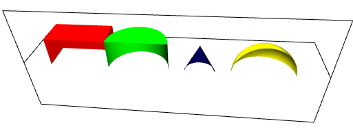
Figure 11.1 illustrates four objects effected by a horizontal clip plane and a vertical clip plane.
A ClipPlane node affects only objects that are in the same transformation hierarchy as the node. Each plane is transformed according to the parent transformation hierarchy but is not further transformed by the children it affects.
Clip planes shall affect nodes derived from X3DBackgroundNode.
Many renderers only support a limited number of clip plane definitions (typically, six). If, while traversing from the root of the scene to a particular leaf, more than the number of supported clip planes are specified, the clip plane definitions closest to the leaf are discarded first (i. e., the clip planes that are closer to the root of the scene graph are considered most important).
11.3 Abstract typesX3DColorNode : X3DGeometricPropertyNode {
SFNode [in,out] metadata NULL [X3DMetadataObject]
}
This is the base node type for color specifications in X3D.
X3DComposedGeometryNode : X3DGeometryNode {
  MFNode [in,out] attrib          []   [X3DVertexAttributeNode]
  SFNode [in,out] color           NULL [X3DColorNode]
  SFNode [in,out] coord           NULL [X3DCoordinateNode]
  SFNode [in,out] fogCoord        NULL [FogCoordinate]
  SFNode [in,out] metadata        NULL [X3DMetadataObject]
  SFNode [in,out] normal          NULL [X3DNormalNode]
  SFNode [in,out] texCoord        NULL [X3DTextureCoordinateNode]
  SFBool []       ccw             TRUE
  SFBool []       colorPerVertex  TRUE
  SFBool []       normalPerVertex TRUE
  SFBool []       solid           TRUE
}
This is the base node type for all composed 3D geometry in X3D.
A composed geometry node type defines an abstract type that composes geometry from a set of nodes that define individual components. Composed geometry may have color, coordinates, normal and texture coordinates supplied. The rendered output of the combination of these is dependent on the concrete node definition. However, in general, the following rules shall be applied for all nodes:
If the attrib field is not empty it shall contain a list of per-vertex attribute information for programmable shaders as specified in 32.2.2.4 Per-vertex attributes.
If the fogCoord field is not empty, it shall contain a list of per-vertex depth values for calculating fog depth as specified in 24.2.2.5 Fog colour calculation.
X3DCoordinateNode : X3DGeometricPropertyNode {
  SFNode [in,out] metadata NULL [X3DMetadataObject]
}
This is the base node type for all coordinate node types in X3D. All coordinates are specified in nodes derived from this abstract node type.
X3DGeometricPropertyNode : X3DNode {
  SFNode [in,out] metadata NULL [X3DMetadataObject]
}
This is the base node type for all geometric property node types defined in X3D
X3DGeometryNode : X3DNode {
  SFNode [in,out] metadata NULL [X3DMetadataObject]
}
This is the base node type for all geometry in X3D.
X3DNormalNode : X3DGeometricPropertyNode {
  SFNode [in,out] metadata NULL [X3DMetadataObject]
}
This is the base node type for all normal node types in X3D. All normals are specified in nodes derived from this abstract node type.
11.4 Node referenceClipPlane : X3DChildNode {
SFBool [in,out] enabled TRUE
SFNode [in,out] metadata NULL [X3DMetadataObject]
SFVec4f [in,out] plane 0 1 0 0 [0,1]
}
The ClipPlane node specifies a single plane equation that will be used to clip the geometry. The plane field specifies a four-component plane equation that describes the inside and outside half space. The first three components are a normalized vector describing the direction of the plane's normal direction.
Color : X3DColorNode {
  MFColor [in,out] color    [NULL] [0,1]
  SFNode  [in,out] metadata NULL   [X3DMetadataObject]
}
This node defines a set of RGB colours to be used in the fields of another node.
Color nodes are only used to specify multiple colours for a single geometric shape, such as colours for the faces or vertices of an IndexedFaceSet. A Material node is used to specify the overall material parameters of lit geometry. If both a Material node and a Color node are specified for a geometric shape, the colours shall replace the diffuse component of the material.
RGB or RGBA textures take precedence over colours; specifying both an RGB or RGBA texture and a Color node for geometric shape will result in the Color node being ignored. Details on lighting equations can be found in 17.2.2 Lighting model.
ColorRGBA : X3DColorNode {
  MFColorRGBA [in,out] color    [NULL] [0,1]
  SFNode      [in,out] metadata NULL   [X3DMetadataObject]
}
This node defines a set of RGBA colours to be used in the fields of another node.
RGBA color nodes are only used to specify multiple colours with alpha for a single geometric shape, such as colours for the faces or vertices of an IndexedFaceSet. A Material node is used to specify the overall material parameters of lit geometry. If both a Material node and a ColorRGBA node are specified for a geometric shape, the colours shall replace the diffuse and transparency components of the material.
RGB or RGBA textures take precedence over colours; specifying both an RGB or RGBA texture and a ColorRGBA node for geometric shape will result in the ColorRGBA node being ignored. Details on lighting equations can be found in 17.2.2 Lighting model.
Coordinate : X3DCoordinateNode {
  SFNode  [in,out] metadata NULL   [X3DMetadataObject]
  MFVec3f [in,out] point    []     (-∞,∞)
}
This node defines a set of 3D coordinates to be used in the coord field of vertex-based geometry nodes including:
IndexedLineSet : X3DGeometryNode {
  MFInt32 [in]     set_colorIndex
  MFInt32 [in]     set_coordIndex
  MFNode  [in,out] attrib         []   [X3DVertexAttributeNode]
  SFNode  [in,out] color          NULL [X3DColorNode]
  SFNode  [in,out] coord          NULL [X3DCoordinateNode]
  SFNode  [in,out] fogCoord       NULL [FogCoordinate]
  SFNode  [in,out] metadata       NULL [X3DMetadataObject]
  MFInt32 []       colorIndex     []   [0,∞) or -1
  SFBool  []       colorPerVertex TRUE
  MFInt32 []       coordIndex     []   [0,∞) or -1
}
The IndexedLineSet node represents a 3D geometry formed by constructing polylines from 3D vertices specified in the coord field. IndexedLineSet uses the indices in its coordIndex field to specify the polylines by connecting vertices from the coord field. An index of "-1" indicates that the current polyline has ended and the next one begins. The last polyline may be (but does not have to be) followed by a "-1". IndexedLineSet is specified in the local coordinate system and is affected by the transformations of its ancestors.
The coord field specifies the 3D vertices of the line set and contains a Coordinate node.
Lines are not lit, are not texture-mapped, and do not participate in collision detection. The width and style of lines are determined by the line properties specified in an associated Appearance node. If no line properties are specified, the default values for fields of the LineProperties node shall be used (see 12.4.3 LineProperties).
If the color field is not NULL, it shall
contain a node derived from X3DColorNode. The colours are applied to the line(s) as follows:
FALSE:
TRUE:
If the color field is NULL and there is a Material defined for the Appearance affecting this IndexedLineSet, the emissiveColor of the Material shall be used to draw the lines. Details on lighting equations as they affect IndexedLineSet nodes are described in 17 Lighting component.
IndexedTriangleFanSet : X3DComposedGeometryNode {
  MFInt32 [in]     set_index       []   [0,∞) or -1
  MFNode  [in,out] attrib          []   [X3DVertexAttributeNode]
  SFNode  [in,out] color           NULL [X3DColorNode]
  SFNode  [in,out] coord           NULL [X3DCoordinateNode]
  SFNode  [in,out] fogCoord        NULL [FogCoordinate]
  SFNode  [in,out] metadata        NULL [X3DMetadataObject]
  SFNode  [in,out] normal          NULL [X3DNormalNode]
  SFNode  [in,out] texCoord        NULL [X3DTextureCoordinateNode]
  SFBool  []       ccw             TRUE
  SFBool  []       colorPerVertex  TRUE
  SFBool  []       normalPerVertex TRUE
  SFBool  []       solid           TRUE
  MFInt32 []       index           []   [0,∞) or -1
}
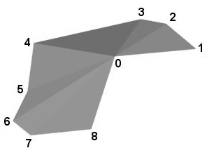
An IndexedTriangleFanSet represents a 3D shape composed of triangles that form a fan shape around the first vertex declared in each fan as depicted in Figure 11.1. IndexedTriangleFanSet uses the indices in its index field to specify the triangle fans by connecting vertices from the coord field. An index of "-1" indicates that the current fan has ended and the next one begins. The last fan may be (but does not have to be) followed by a "-1".Each fan shall have at least three non-coincident vertices.
The IndexedTriangleFanSet node is specified in the local coordinate system and is affected by the transformations of its ancestors. Descriptions of the color, coord, normal, and texCoord fields are provided in the Color, ColorRGBA, Coordinate, Normal, and TextureCoordinate nodes, respectively. If values are provided for the color, normal and texCoord fields, the values are applied in the same manner as the values from the coord field and there shall be at least as many values as are present in the coord field. The value of the colorPerVertex field is ignored and always treated as TRUE. If the normal field is not provided, normals shall be generated as follows:
The solid field determines whether the IndexedTriangleFanSet is visible when viewed from the inside. 11.2.3 Common geometry fields provides a complete description of the solid field.
IndexedTriangleSet : X3DComposedGeometryNode {
  MFInt32 [in]     set_index       []   [0,∞)
  MFNode  [in,out] attrib          []   [X3DVertexAttributeNode]
  SFNode  [in,out] color           NULL [X3DColorNode]
  SFNode  [in,out] coord           NULL [X3DCoordinateNode]
  SFNode  [in,out] fogCoord        NULL [FogCoordinate]
  SFNode  [in,out] metadata        NULL [X3DMetadataObject]
  SFNode  [in,out] normal          NULL [X3DNormalNode]
  SFNode  [in,out] texCoord        NULL [X3DTextureCoordinateNode]
  SFBool  []       ccw             TRUE
  SFBool  []       colorPerVertex  TRUE
  SFBool  []       normalPerVertex TRUE
  SFBool  []       solid           TRUE
  MFInt32 []       index           []   [0,∞)
}
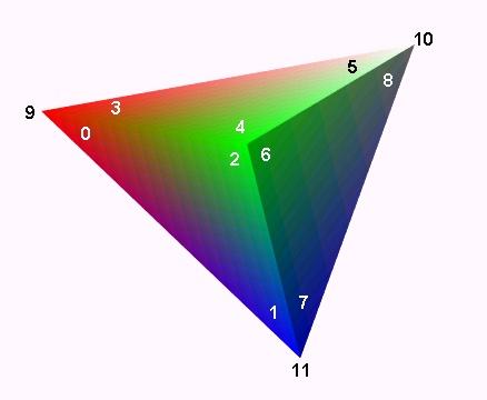
The IndexedTriangleSet node represents a 3D shape composed of a collection of individual triangles as depicted in Figure 11.2. IndexedTriangleSet uses the indices in its index field to specify the vertices of each triangle from the coord field. Each triangle is formed from a set of three vertices of the Coordinate node identified by three consecutive indices from the index field. If the index field does not contain a multiple of three coordinate values, the remaining vertices shall be ignored.
The IndexedTriangleSet node is specified in the local coordinate system and is affected by the transformations of its ancestors. Descriptions of the color, coord, normal, and texCoord fields are provided in the Color, ColorRGBA, Coordinate, Normal, and TextureCoordinate nodes, respectively. If values are provided for the color, normal and texCoord fields, the values are applied in the same manner as the values from the coord field and there shall be at least as many values as are present in the coord field. The value of the colorPerVertex field is ignored and always treated as TRUE. If the normal field is not supplied, normals shall be generated as follows:
The solid field determines whether the IndexedTriangleSet is visible when viewed from the backside. 11.2.3 Common geometry fields provides a complete description of the solid field.
IndexedTriangleStripSet : X3DComposedGeometryNode {
  MFInt32 [in]     set_index       []   [0,∞) or −1
  MFNode  [in,out] attrib          []   [X3DVertexAttributeNode]
  SFNode  [in,out] color           NULL [X3DColorNode]
  SFNode  [in,out] coord           NULL [X3DCoordinateNode]
  SFNode  [in,out] fogCoord        NULL [FogCoordinate]
  SFNode  [in,out] metadata        NULL [X3DMetadataObject]
  SFNode  [in,out] normal          NULL [X3DNormalNode]
  SFNode  [in,out] texCoord        NULL [X3DTextureCoordinateNode]
  SFBool  []       ccw             TRUE
  SFBool  []       colorPerVertex  TRUE
  SFBool  []       normalPerVertex TRUE
  SFBool  []       solid           TRUE
  MFInt32 []       index           []   [0,∞) or −1
}
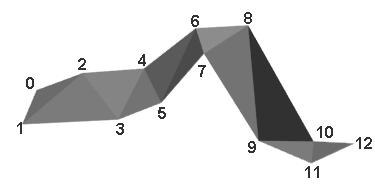
An IndexedTriangleStripSet represents a 3D shape composed of strips of triangles as depicted in Figure 11.3. IndexedTriangleStripSet uses the indices in its index field to specify the triangle strips by connecting vertices from the coord field. An index of "−1" indicates that the current strip has ended and the next one begins. The last strip may be (but does not have to be) followed by a "−1". Each strip shall have at least three non-coincident vertices.
The IndexedTriangleStripSet node is specified in the local coordinate system and is affected by the transformations of its ancestors. Descriptions of the color, coord, normal, and texCoord fields are provided in the Color, ColorRGBA, Coordinate, Normal, and TextureCoordinate nodes, respectively. If values are provided for the color, normal and texCoord fields, the values are applied in the same manner as the values from the coord field and there shall be at least as many values as are present in the coord field. The value of the colorPerVertex field is ignored and always treated as TRUE. If the normal field is not supplied, normals shall be generated as follows:
The solid field determines whether the IndexedTriangleStripSet is visible when viewed from the inside. 11.2.3 Common geometry fields provides a complete description of the solid field.
LineSet : X3DGeometryNode {
  MFNode  [in,out] attrib         []   [X3DVertexAttributeNode]
  SFNode  [in,out] color          NULL [X3DColorNode]
  SFNode  [in,out] coord          NULL [X3DCoordinateNode]
  SFNode  [in,out] fogCoord       NULL [FogCoordinate]
  SFNode  [in,out] metadata       NULL [X3DMetadataObject]
  MFInt32 [in,out] vertexCount    []   [2,∞)
}
The LineSet node represents a 3D geometry formed by constructing polylines from 3D vertices specified in the coord field.
The color field specifies the colour of the line set at each vertex and contains a node derived from X3DColorNode. A description of the color field is provided in the color node. If the color field is NULL and there is a Material defined for the Appearance affecting this LineSet, the emissiveColor of the Material shall be used to draw the lines. Details on lighting equations as they affect LineSet nodes are described in 17 Lighting component
The coord field specifies the 3D vertices of the line set and contains a Coordinate node.
The vertexCount field describes how many vertices are to be used in each polyline from the coordinate field. Coordinates are assigned to each line by taking vertexCount[n] vertices from the coordinate field. Each value of the vertexCount array shall be greater than or equal to two. It shall be an error to have a value less than two.
Lines are not lit, are not texture-mapped, and do not participate in collision detection. The width and style of lines are determined by the line properties specified in an associated Appearance node. If no line properties are specified, the default values for the fields of the LineProperties node shall be used (see 12.4.3 LineProperties).
Normal : X3DNormalNode {
  SFNode  [in,out] metadata NULL [X3DMetadataObject]
  MFVec3f [in,out] vector   []   [-1,1]
}
This node defines a set of 3D surface normal vectors to be used in the vector field of some geometry nodes (EXAMPLE IndexedFaceSet and ElevationGrid). This node contains one multiple-valued field that contains the normal vectors. Normals shall be of unit length.
PointSet : X3DGeometryNode {
  MFNode [in,out] attrib   []   [X3DVertexAttributeNode]
  SFNode [in,out] color    NULL [X3DColorNode]
  SFNode [in,out] coord    NULL [X3DCoordinateNode]
  SFNode [in,out] fogCoord NULL [FogCoordinate]
  SFNode [in,out] metadata NULL [X3DMetadataObject]
}
The PointSet node specifies a set of 3D points, in the local coordinate system,
with associated colours at each point. The coord field specifies a
Coordinate
node (or instance of a Coordinate node). The results are undefined if the coord
field specifies any other type of node. PointSet uses the coordinates in order.
If the coord field is NULL, the point
set is considered empty.
PointSet nodes are not lit, not texture-mapped, nor do they participate in collision detection. The size of each point is implementation-dependent.
If the color field is not NULL, it shall
specify a node derived from X3DColorNode that contains at least the number of points contained in
the coord node. The results are undefined if the color field specifies
any other type of node. Colours shall be applied to each point in order. The
results are undefined if the number of values in the X3DColorNode node is less than
the number of values specified in the Coordinate node.
If the color field is NULL and there is a Material node defined for the Appearance node affecting this PointSet node, the emissiveColor of the Material node shall be used to draw the points. More details on lighting equations can be found 17 Lighting component.
TriangleFanSet : X3DComposedGeometryNode {
  MFNode  [in,out] attrib          []   [X3DVertexAttributeNode]
  SFNode  [in,out] color           NULL [X3DColorNode]
  SFNode  [in,out] coord           NULL [X3DCoordinateNode]
  MFInt32 [in,out] fanCount        []   [3,∞)
  SFNode  [in,out] fogCoord        NULL [FogCoordinate]
  SFNode  [in,out] metadata        NULL [X3DMetadataObject]
  SFNode  [in,out] normal          NULL [X3DNormalNode]
  SFNode  [in,out] texCoord        NULL [X3DTextureCoordinateNode]
  SFBool  []       ccw             TRUE
  SFBool  []       colorPerVertex  TRUE
  SFBool  []       normalPerVertex TRUE
  SFBool  []       solid           TRUE
}
A TriangleFanSet represents a 3D shape composed of triangles that form a fan shape around the first vertex declared in each fan.
The fanCount field describes how many vertices are to be used in each fan from the coordinate field. Coordinates are assigned to each strip by taking fanCount[n] vertices from the coordinate field. Each value of the fanCount array shall be greater than or equal to three. It shall be an error to have a value less than three.
Figure 11.2 displays a TriangleFanSet containing a single fan showing the ordering of the vertices for that fan.
The TriangleFanSet node is specified in the local coordinate system and is affected by the transformations of its ancestors. Descriptions of the color, coord, normal, and texCoord fields are provided in the Color/ColorRGBA, Coordinate, Normal, and TextureCoordinate nodes, respectively. If values are provided for the color, normal, and texCoord fields, there shall be at least as many values as are present in the coord field. The value of the colorPerVertex field is ignored and always treated as TRUE. If the normal field is not provided, for each fan, the normal shall be generated as follows: if normalPerVertex is TRUE, the normal shall be the average of all triangles within that fan sharing that vertex. For the vertex of the fan, the normal shall be the average of the contributions of all of the individual face normals. If normalPerVertex is FALSE, the normal shall be generated for the current triangle based on the ccw field.
The solid field determines whether the TriangleFanSet is visible when viewed from the inside. 11.2.3 Common geometry fields provides a complete description of the solid field.
TriangleSet : X3DComposedGeometryNode {
  MFNode  [in,out] attrib          []   [X3DVertexAttributeNode]
  SFNode  [in,out] color           NULL [X3DColorNode]
  SFNode  [in,out] coord           NULL [X3DCoordinateNode]
  SFNode  [in,out] fogCoord        NULL [FogCoordinate]
  SFNode  [in,out] metadata        NULL [X3DMetadataObject]
  SFNode  [in,out] normal          NULL [X3DNormalNode]
  SFNode  [in,out] texCoord        NULL [X3DTextureCoordinateNode]
  SFBool  []       ccw             TRUE
  SFBool  []       colorPerVertex  TRUE
  SFBool  []       normalPerVertex TRUE
  SFBool  []       solid           TRUE
}
The TriangleSet node represents a 3D shape that represents a collection of individual triangles.
The coord field contains a Coordinate node that defines the 3D vertices that define the triangle. Each triangle is formed from a consecutive set of three vertices of the Coordinate node. If the Coordinate node does not contain a multiple of three coordinate values, the remaining vertices shall be ignored.
Figure 11.3 depicts a TriangleSet node with
several triangles. The ordering of the vertices is also shown.
The TriangleSet node is specified in the local coordinate system and is affected by the transformations of its ancestors. Descriptions of the color, coord, normal, and texCoord fields are provided in the Color/ColorRGBA, Coordinate, Normal, and TextureCoordinate nodes, respectively. If values are provided for the color, normal, and texCoord fields, there shall be at least as many values as are present in the coord field. The value of the colorPerVertex field is ignored and always treated as TRUE. If the normal field is not supplied, the normal shall be generated as perpendicular to the face for either version of normalPerVertex.
The solid field determines whether the TriangleSet is visible when viewed from the backside. 11.2.3 Common geometry fields provides a complete description of the solid field.
TriangleStripSet : X3DComposedGeometryNode {
  MFNode  [in,out] attrib          []   [X3DVertexAttributeNode]
  SFNode  [in,out] color           NULL [X3DColorNode]
  SFNode  [in,out] coord           NULL [X3DCoordinateNode]
  SFNode  [in,out] fogCoord        NULL [FogCoordinate]
  SFNode  [in,out] metadata        NULL [X3DMetadataObject]
  SFNode  [in,out] normal          NULL [X3DNormalNode]
  MFInt32 [in,out] stripCount      []   [3,∞)
  SFNode  [in,out] texCoord        NULL [X3DTextureCoordinateNode]
  SFBool  []       ccw             TRUE
  SFBool  []       colorPerVertex  TRUE
  SFBool  []       normalPerVertex TRUE
  SFBool  []       solid           TRUE
}
A TriangleStripSet represents a 3D shape composed of strips of triangles.
The stripCount field describes how many vertices are to be used in each
strip from the coordinate field. Coordinates are assigned to each strip by taking
stripCount[i] vertices from the coordinate field, where i is a
sequential index of stripCount. Each value of the stripCount
array shall be greater than or equal to three. It shall be an error to have
a value less than three. Figure 11.4 depicts
a TriangleStripSet with a single triangle strip.
The TriangleStripSet node is specified in the local coordinate system and is affected by the transformations of its ancestors. Descriptions of the color, coord, normal, and texCoord fields are provided in the Color/ColorRGBA, Coordinate, Normal, and TextureCoordinate nodes, respectively. If values are provided for the color, normal, and texCoord fields, there shall be at least as many values as are present in the coord field. The value of the colorPerVertex field is ignored and always treated as TRUE. If the normal field is not provided, for each strip, the normal shall be generated as follows: if normalPerVertex is TRUE, the normal shall be the average of all triangles within that strip sharing that vertex. If normalPerVertex is FALSE, the normal shall be generated for the triangle based on the ccw field.
The solid field determines whether the TriangleStripSet is visible when viewed from the inside. 11.2.3 Common geometry fields provides a complete description of the solid field.
11.5 Support levelsThe Rendering component provides three levels of support as specified in Table 11.2.
Table 11.2 — Rendering component support levels
| Level | Prerequisites | Nodes/Features | Support |
|---|---|---|---|
|
1 |
Core 1 Grouping 1 |
||
| X3DComposedGeometryNode (abstract) | n/a | ||
| X3DGeometricPropertyNode (abstract) | n/a | ||
| X3DGeometryNode (abstract) | n/a | ||
| X3DColorNode (abstract) | n/a | ||
| X3DCoordinateNode (abstract) | n/a | ||
| Color | All fields fully supported. | ||
| ColorRGBA | Alpha value optionally supported. | ||
| Coordinate | All fields fully supported. | ||
| IndexedLineSet | set_colorIndex optionally supported. set_coordIndex optionally supported. | ||
| LineSet | All fields fully supported. | ||
| PointSet | All fields fully supported. | ||
| 2 | Core 1 Grouping 1 |
||
| All Level 1 Rendering nodes | All fields as supported in Level 1. | ||
| X3DNormalNode (abstract) | n/a | ||
| Normal | All fields fully supported. | ||
| 3 | Core 1 Grouping 1 |
||
| All Level 2 Rendering nodes | All fields fully supported except for ColorRGBA supported as in Level 2. | ||
| IndexedTriangleFanSet | All fields fully supported. | ||
| IndexedTriangleSet | All fields fully supported. | ||
| IndexedTriangleStripSet | All fields fully supported. | ||
| TriangleFanSet | All fields fully supported. | ||
| TriangleSet | All fields fully supported. | ||
| TriangleStripSet | All fields fully supported. | ||
| 4 | Core 1 Grouping 1 |
||
| All Level 3 Rendering nodes | All fields as supported in Level 3. | ||
| ColorRGBA | Alpha value fully supported. | ||
|
5 |
Core 1 Grouping 1 |
||
| All Level 4 Rendering nodes | All fields as supported in Level 4. | ||
| ClipPlane | All fields fully supported. |