Extensible 3D (X3D)
Part 1: Architecture and base components
12 Shape component
The name of this component is "Shape". This name shall be used when referring to this component in the COMPONENT statement (see 7.2.5.4 Component statement).
This clause describes the Shape component of this part of ISO/IEC 19775. The Shape component defines nodes for associating geometry with their visible properties and the scene environment. Table 12.1 provides links to the major topics in this clause.
The Shape node associates a geometry node with nodes that define that geometry's appearance. Shape nodes shall be part of the transformation hierarchy to have any visible result, and the transformation hierarchy shall contain Shape nodes for any geometry to be visible (the only nodes that render visible results are Shape nodes and the background nodes described in 24 Environmental effects). A Shape node contains exactly one geometry node in its geometry field, which is of type X3DGeometryNode. The Shape node descends from the abstract base type X3DShapeNode.
Shape nodes may specify an Appearance node that describes the appearance properties (material, texture and texture transformation) to be applied to the Shape's geometry. All valid children of the Appearance node descend from the abstract base type X3DAppearanceChildNode.
Nodes of the following types may be specified in the material field of the Appearance node:
This set may be extended by creating new nodes derived from the X3DMaterialNode abstract base type.
The Appearance node specifies texture mapping in its texture field. Valid values of the texture field are descendants of X3DTextureNode, including:
This set may be extended by creating new nodes derived from the abstract X3DTextureNode base class as defined in 18.3.2 X3DTextureNode.
Nodes of the type X3DTextureTransformNode may be specified in the textureTransform field of the Appearance node (see 18.3.4 X3DTextureTransformNode), including:
The interaction between the appearance properties and properties specific to geometry nodes is described in 13 Geometry3D component and 14 Geometry2D component
An Appearance node ,may specify additional information about the appearance of the geometry. Special properties may be defined for lines and filled areas. These properties are defined in the lineProperties and fillProperties fields by the following nodes, respectively:
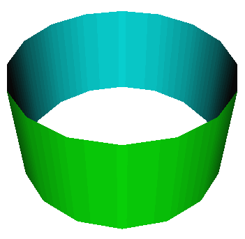
A polygon defines a front face based on the direction of the normal. That normal is either explicitly provided by the end user or implicitly calculated by the browser based on the winding rules for the node (see the ccw field on many of the polygonal geometry nodes such as IndexedFaceSet). The TwoSidedMaterial node provides a way to render the front and back sides of the polygon with different material properties. Figure 12.1 depicts the effects of the TwoSidedMaterial node.
When the back side of the material is rendered using the alternate colours, the rendering shall follow the normal lighting equations for lit geometry.
X3DAppearanceChildNode : X3DNode {
  SFNode [in,out] metadata NULL [X3DMetadataObject]
}
This is the base node type for the child nodes of the X3DAppearanceNode type.
X3DAppearanceNode : X3DNode {
  SFNode [in,out] metadata NULL [X3DMetadataObject]
}
This is the base node type for all Appearance nodes.
X3DMaterialNode : X3DAppearanceChildNode {
  SFNode [in,out] metadata NULL [X3DMetadataObject]
}
This is the base node type for all Material nodes.
X3DShapeNode : X3DChildNode, X3DBoundedObject {
  SFNode  [in,out] appearance NULL     [X3DAppearanceNode]
  SFNode  [in,out] geometry   NULL     [X3DGeometryNode]
  SFNode  [in,out] metadata   NULL     [X3DMetadataObject]
  SFVec3f []       bboxCenter 0 0 0    (-∞,∞)
  SFVec3f []       bboxSize   -1 -1 -1 [0,∞) or −1 −1 −1
}
This is the base node type for all Shape nodes.
Appearance : X3DAppearanceNode {
  SFNode [in,out] fillProperties   NULL [FillProperties]
  SFNode [in,out] lineProperties   NULL [LineProperties]
  SFNode [in,out] material         NULL [X3DMaterialNode]
  SFNode [in,out] metadata         NULL [X3DMetadataObject]
  MFNode [in,out] shaders          []   [X3DShaderNode]
  SFNode [in,out] texture          NULL [X3DTextureNode]
  SFNode [in,out] textureTransform NULL [X3DTextureTransformNode]
}
The Appearance node specifies the visual properties of geometry.
The value for each of the fields in this node may be NULL.
However, if the field is non-NULL, it shall
contain one node of the appropriate type.
The material field, if specified, shall contain a Material
node. If the material field is NULL or
unspecified, lighting is off (all lights are ignored during rendering of the
object that references this Appearance) and the unlit object colour is (1, 1, 1).
Details of the X3D lighting model are in
17 Lighting component.
The texture field, if specified, shall contain one of the various
types of texture nodes
(see
18 Texturing component).
If the texture node is NULL or the texture
field is unspecified, the object that references this Appearance is not textured.
The textureTransform field, if specified, shall contain
a TextureTransform node as defined in
18.4.8 TextureTransform. If the textureTransform is
NULL or unspecified, the textureTransform field has no effect.
The lineProperties field, if specified, shall contain a
LineProperties node as specified in 12.4.3
LineProperties. If lineProperties is
NULL or unspecified, the lineProperties
field has no effect.
The fillProperties field, if specified, shall contain a
FillProperties node as specified in 12.4.2
FillProperties. If fillProperties is
NULL or unspecified, the fillProperties
field has no effect.
The shaders field contains a listing, in order of preference, of nodes that describe programmable shaders that replace the fixed rendering requirements of this part of ISO/IEC 19775 with user-provided functionality. If the field is not empty, one shader node is selected and the fixed rendering requirements defined by this specification are ignored. The field shall contain one of the various types of shader nodes as specified in 31 Programmable shaders component.
FillProperties : X3DAppearanceChildNode {
  SFBool  [in,out] filled     TRUE
  SFColor [in,out] hatchColor 1 1 1 [0,1]
  SFBool  [in,out] hatched    TRUE
  SFInt32 [in,out] hatchStyle 1     [0,∞)
  SFNode  [in,out] metadata   NULL  [X3DMetadataObject]
}
The FillProperties node specifies additional properties to be applied to all polygonal areas on top of whatever appearance is specified by the other fields of the respective Appearance node. Thus, hatches are applied on top of the already rendered appearance of the node. Thus, if filled is TRUE, the polygonal area is filled according to the other fields of the Appearance node. If hatched is TRUE, the polygonal area is hatched as specified by the hatchStyle field. Hatches shall be applied after fills are applied.
The hatchStyle field selects a hatch pattern as defined in the International Register of Graphical Items (see 2.[REG]). The hatches are rendered using the colour specified by the hatchColor field. Browsers shall support hatchstyles 1-6 with hatchstyle 1 being the default. X3D browsers may support any other of the registered hatchstyles. If a hatchstyle that is not supported is requested, hatchstyle 1 shall be used. Table 12.2 specifies the first nineteen hatch styles as defined in the Hatchstyle Section of the International Register of Items. Examples of each hatch style are available at the International Register of Items.
Table 12.2 — International registry of items hatchstyles
| 1 | Horizontal equally spaced parallel lines |
| 2 | Vertical equally spaced parallel lines |
| 3 | Positive slope equally spaced parallel lines |
| 4 | Negative slope equally spaced parallel lines |
| 5 | Horizontal/vertical crosshatch |
| 6 | Positive slope/negative slope crosshatch |
| 7 | (cast iron or malleable iron and general use for all materials) |
| 8 | (steel) |
| 9 | (bronze, brass, copper, and compositions) |
| 10 | (white metal, zinc, lead, babbit, and alloys) |
| 11 | (magnesium, aluminum, and aluminum alloys) |
| 12 | (rubber, plastic, and electrical insulation) |
| 13 | (cork,felt, fabric, leather, and fibre) |
| 14 | (thermal insulation) |
| 15 | (titanium and refractory material) |
| 16 | (marble, slate, porcelain, glass, etc.) |
| 17 | (earth) |
| 18 | (sand) |
| 19 | (repeating dot) |
The associated geometry shall be filled and/or hatched only when the respective values of the filled and/or hatched fields have value TRUE.
LineProperties : X3DAppearanceChildNode {
  SFBool  [in,out] applied              TRUE
  SFInt32 [in,out] linetype             1    [1,∞)
  SFFloat [in,out] linewidthScaleFactor 0    (-∞,∞)
  SFNode  [in,out] metadata             NULL [X3DMetadataObject]
}
The LineProperties node specifies additional properties to be applied to all line geometry. The linetype and linewidth shall only be applied when the applied field has value TRUE. When the value of the applied field is FALSE, a solid line of nominal width shall be produced. The colour of the line is specified by the associated Material node.
The linetype field selects a line pattern as defined in the International Register of Graphical Items (see 2.[REG]). X3D browsers shall support linetypes 1 through 5 with linetype 1 being the default. X3D browsers may support any other of the registered linetypes. If a linetype that is not supported is requested, linetype 1 shall be used. Table 12.2 specifies the first sixteen linetypes as defined in the Linetype Section of the International Register of Items.
Table 12.3 — International registry of items linetypes
| 1 | Solid |
| 2 | Dashed |
| 3 | Dotted |
| 4 | Dashed-dotted |
| 5 | Dash-dot-dot |
| 6 | (single arrow) |
| 7 | (single dot) |
| 8 | (double arrow) |
| 10 | (chain line) |
| 11 | (center line) |
| 12 | (hidden line) |
| 13 | (phantom line) |
| 14 | (break line 1) |
| 15 | (break line 2) |
| 16 | User-specified dash pattern |
The arrowhead is drawn as short lines forming barbs at any convenient angle between 15 and 90 degrees. The arrowhead is closed and filled in. For linetype "single arrow", the arrowhead is rendered so that the arrow tip occurs at the last point of the each individual list of points passed to a polyline and is in the direction of the last vector. For linetype "double arrow", the first arrowhead is rendered so that the arrow tip occurs at the first point of the list of points passed to a polyline and is in the reverse direction of the first vector. The second arrowhead is rendered as for "single arrow" at the opposite end of the polyline.
The linewidthScaleFactor is a multiplicative value that scales a browser dependent nominal linewidth by the linewidth scale factor. This resulting value shall then be mapped to the nearest available line width. A value less than or equal to zero refers to the minimum available line width.
Material : X3DMaterialNode {
  SFFloat [in,out] ambientIntensity 0.2         [0,1]
  SFColor [in,out] diffuseColor     0.8 0.8 0.8 [0,1]
  SFColor [in,out] emissiveColor    0 0 0       [0,1]
  SFNode  [in,out] metadata         NULL        [X3DMetadataObject]
  SFFloat [in,out] shininess        0.2         [0,1]
  SFColor [in,out] specularColor    0 0 0       [0,1]
  SFFloat [in,out] transparency     0           [0,1]
}
The Material node specifies surface material properties for associated geometry nodes and is used by the X3D lighting equations during rendering. 17 Lighting component contains a detailed description of the X3D lighting model equations.
All of the fields in the Material node range from 0.0 to 1.0.
The fields in the Material node determine how light reflects off an object to create colour:
Shape : X3DShapeNode {
  SFNode  [in,out] appearance NULL     [X3DAppearanceNode]
  SFNode  [in,out] geometry   NULL     [X3DGeometryNode]
  SFNode  [in,out] metadata   NULL     [X3DMetadataObject]
  SFVec3f []       bboxCenter 0 0 0    (-∞,∞)
  SFVec3f []       bboxSize   -1 -1 -1 [0,∞) or −1 −1 −1
}
The Shape node has two fields, appearance and geometry, that are used to create rendered objects in the world. The appearance field contains an Appearance node that specifies the visual attributes (e.g., material and texture) to be applied to the geometry. The geometry field contains a geometry node. The specified geometry node is rendered with the specified appearance nodes applied. See 12.2 Concepts for more information.
17 Lighting component contains details of the X3D lighting model and the interaction between Appearance nodes and geometry nodes.
If the geometry field is NULL, the object is not drawn.
The bboxCenter and bboxSize fields specify a bounding box that encloses the Shape node's geometry. This is a hint that may be used for optimization purposes. The results are undefined if the specified bounding box is smaller than the actual bounding box of the geometry at any time. A default bboxSize value, (-1, -1, -1), implies that the bounding box is not specified and, if needed, is calculated by the browser. A description of the bboxCenter and bboxSize fields is contained in 10.2.2 Bounding boxes.
TwoSidedMaterial : X3DMaterialNode {
  SFFloat [in,out] ambientIntensity     0.2         [0,1]
  SFFloat [in,out] backAmbientIntensity 0.2         [0,1]
  SFColor [in,out] backDiffuseColor     0.8 0.8 0.8 [0,1]
  SFColor [in,out] backEmissiveColor    0 0 0       [0,1]
  SFFloat [in,out] backShininess        0.2         [0,1]
  SFColor [in,out] backSpecularColor    0 0 0       [0,1]
  SFFloat [in,out] backTransparency     0           [0,1]
  SFColor [in,out] diffuseColor         0.8 0.8 0.8 [0,1]
  SFColor [in,out] emissiveColor        0 0 0       [0,1]
  SFNode  [in,out] metadata             NULL        [X3DMetadataObject]
  SFFloat [in,out] shininess            0.2         [0,1]
  SFBool  [in,out] separateBackColor    FALSE
  SFColor [in,out] specularColor        0 0 0       [0,1]
  SFFloat [in,out] transparency         0           [0,1]
}
This node defines material properties that can effect both the front and back side of a polygon individually. These materials are used for both the front and back side of the geometry whenever the X3D lighting model is active.
If the separateBackColor field is set to TRUE, the rendering shall render the front and back faces of the geometry with different values. If the value is FALSE, the front colours are used for both the front and back side of the polygon, as per the existing X3D lighting rules.
When calculating the terms in the lighting equations, the front geometry shall use the fields ambientIntensity, diffuseColor,emissiveColor, shininess, specularColor, and transparency. The faces that are determined to be the back side are rendered using backAmbientIntensity, backDiffuseColor, backEmissiveColor, backShininess, and backTransparency as the appropriate components in the lighting equations.
The Shape component provides three levels of support as specified in Table 12.4.
Table 12.4 — Shape component support levels
| Level | Prerequisites | Nodes/Features | Support |
|---|---|---|---|
| 1 | Core 1 Rendering 1 Texturing 1 |
||
| X3DAppearanceChildNode(abstract) | n/a | ||
| X3DAppearanceNode (abstract) | n/a | ||
| X3DMaterialNode (abstract) | n/a | ||
| X3DShapeNode (abstract) | n/a | ||
| Appearance | textureTransform optionally supported. lineProperties not supported. fillProperties not supported. Shaders not supported. |
||
| Material | ambientIntensity optionally supported. shininess optionally supported. specularColour optionally supported. A Material with emissiveColour not equal to (0,0,0), diffuseColor equal to (0,0,0) is an unlit material. One-bit transparency; transparency values ≥ 0.5 transparent. | ||
| Shape | All fields fully supported. | ||
| 2 | Core 1 Rendering 1 Texturing 1 |
All fields fully supported. | |
| All Level 1 Appearance nodes except Appearance | All fields fully supported. | ||
| Appearance | fillProperties not supported. Shaders not supported. | ||
| LineProperties | All fields fully supported. | ||
| 3 | Core 1 Rendering 1 Texturing 1 |
||
| All Level 2 Appearance nodes | All fields fully supported. | ||
| FillProperties | All fields fully supported. | ||
| 4 | Core 1 Grouping 1 Rendering 1 |
||
| All Level 3 Appearance nodes | All fields fully supported. | ||
| TwoSidedMaterial | All fields fully supported. |