Extensible 3D (X3D)
Part 1: Architecture and base components
32 CAD geometry component
 32.1 Introduction
The name of this component is "CADGeometry". The CADGeometry component provides X3D support for Computer-Aided Design (CAD) model geometry. This name shall be used when referring to this component in the COMPONENT statement (see 7.2.5.4 Component statement).
This clause describes the CADGeometry component of this part of ISO/IEC 19775. This includes how 3D geometry is specified and what shapes are available. Table 32.1 provides links to the major topics in this clause.
32.2 ConceptsThe CADGeometry component consists of two types of nodes: product structure nodes and quad geometry nodes. Together, these node types are used to describe CAD specific data representations for X3D worlds.
This hierarchy structures the file in a way that facilitates reuse of the CAD data in different domains.
The CADLayer node maintains CAD layer relationships. CAD layers are used to visually and/or functionally organize geometric content.
Quad nodes represent collections of planar quadrilateral polygons. The IndexedQuadSet node specifies the vertices using indices while the QuadSet node specifies the vertices directly.
Several 3D CADGeometry nodes share common fields to describe attributes. These fields that specify the vertex ordering and whether the shape is solid are named ccw and solid respectively. Common 3D geometry fields are described in 11.2.3 Common geometry fields.
32.3 Abstract types
X3DProductStructureChildNode : X3DChildNode {
  SFNode   [in,out] metadata NULL [X3DMetadataObject]
  SFString [in,out] name     ""
}
The X3DProductStructureChildNode abstract node type marks nodes that are valid product structure children.
32.4 Node referenceCADAssembly : X3DGroupingNode, X3DProductStructureChildNode {
MFNode [in] addChildren
MFNode [in] removeChildren
MFNode [in,out] children [] [X3DProductStructureChildNode, X3DGroupingNode]
SFNode [in,out] metadata NULL [X3DMetadataObject]
SFString [in,out] name ""
SFVec3f [] bboxCenter 0 0 0 (-∞,∞)
SFVec3f [] bboxSize -1 -1 -1 [0,∞) or −1 −1 −1
}
The CADAssembly node holds a set of assemblies or parts grouped together.
The children field can contain X3DProductStructureChildNode types. Each child will be either a sub-assembly or a part.The name field specifies the name of the CADAssembly.
CADFace : X3DProductStructureChildNode, X3DBoundedObject {
  SFNode   [in,out] metadata   NULL     [X3DMetadataObject]
  SFString [in,out] name       ""
  SFNode   [in,out] shape      NULL     [X3DShapeNode, LOD, Transform]
  SFVec3f  []       bboxCenter 0 0 0    (-∞, ∞)
  SFVec3f  []       bboxSize   -1 -1 -1 [0, ∞) or -1 -1 -1
}
The CADFace node holds the geometry representing a face of a part.
The name field specifies the name of the CADFace.The shape field contains the Shape node providing the geometry and appearance for the face or an LOD node containing different detail levels of the shape. If an LOD node is provided, each child of the LOD node shall be a single Shape of varying complexity. If the shape field contains a Transform node, the Transform node can only contain one Shape node or else one LOD node as specified above. Thus, only one Shape is ever active at a single time.
CADLayer : X3DGroupingNode {
  MFNode   [in]     addChildren
  MFNode   [in]     removeChildren
  MFNode   [in,out] children       []       [X3DChildNode]
  SFNode   [in,out] metadata       NULL     [X3DMetadataObject]
  SFString [in,out] name           ""
  MFBool   [in,out] visible        []
  SFVec3f  []       bboxCenter     0 0 0    (-∞,∞)
  SFVec3f  []       bboxSize       -1 -1 -1 [0,∞) or −1 −1 −1
}
The CADLayer node defines a hierarchy of nodes used for showing layer structure for the CAD model.
The name field describes the content of the layer.The children field contains all nodes defined for this layer.
The visible field specifies whether a particular child and its sub-children are visible. If the number of values is less than the number of children, the remaining children shall be visible.
CADPart : X3DGroupingNode, X3DProductStructureChildNode {
  MFNode     [in]     addChildren
  MFNode     [in]     removeChildren
  SFVec3f    [in,out] center           0 0 0    (-∞,∞)
  MFNode     [in,out] children         []       [CADFace]
  SFNode     [in,out] metadata         NULL     [X3DMetadataObject]
  SFString   [in,out] name             ""
  SFRotation [in,out] rotation         0 0 1 0  [-1,1] or (-∞,∞)
  SFVec3f    [in,out] scale            1 1 1    (0,∞)
  SFRotation [in,out] scaleOrientation 0 0 1 0  [-1,1] or (-∞,∞)
  SFVec3f    [in,out] translation      0 0 0    (-∞,∞)
  SFVec3f    []       bboxCenter       0 0 0    (-∞,∞)
  SFVec3f    []       bboxSize         -1 -1 -1 [0,∞) or −1 −1 −1
}
The CADPart node is a grouping node that defines a coordinate system for its children that is relative to the coordinate systems of its ancestors. See 4.3.5 Transformation hierarchy and 4.3.6 Standard units and coordinate system for a description of coordinate systems and transformations.
The CADPart node represents the location and faces that constitute a part in the CAD model.
10.2.1 Grouping and children node types provides a description of the children, addChildren, and removeChildren fields.
The bboxCenter and bboxSize fields specify a bounding box that encloses the children of the Part node. This is a hint that may be used for optimization purposes. The results are undefined if the specified bounding box is smaller than the actual bounding box of the children at any time. A default bboxSize value, (-1, -1, -1), implies that the bounding box is not specified and, if needed, shall be calculated by the browser. The bounding box shall be large enough at all times to enclose the union of the group's children's bounding boxes; it shall not include any transformations performed by the group itself (i.e., the bounding box is defined in the local coordinate system of the children).
The translation, rotation, scale, scaleOrientation and center fields define a geometric 3D transformation consisting of (in order):
The center field specifies a translation offset from the origin of the local coordinate system (0,0,0). The rotation field specifies a rotation of the coordinate system. The scale field specifies a non-uniform scale of the coordinate system. The scale field may have values that are positive, negative (indicating a reflection), or zero. A value of zero indicates that any child geometry shall not be displayed. The scaleOrientation specifies a rotation of the coordinate system before the scale (to specify scales in arbitrary orientations). The scaleOrientation applies only to the scale operation. The translation field specifies a translation to the coordinate system.
Given a 3-dimensional point P and Part node, P is transformed into point P' in its parent's coordinate system by a series of intermediate transformations. In matrix transformation notation, where C (center), SR (scaleOrientation), T (translation), R (rotation), and S (scale) are the equivalent transformation matrices,
P' = T * C * R * SR * S * -SR * -C * P
The following Part node:
CADPart {
  center           C
  rotation         R
  scale            S
  scaleOrientation SR
  translation      T
  children         [...]
}
is equivalent to the nested sequence of:
CADPart {
  translation T
  children CADPart {
    translation C
    children CADPart {
      rotation R
      children CADPart {
        rotation SR
        children CADPart {
          scale S
          children CADPart {
            rotation -SR
            children CADPart {
              translation -C
              children [...]
}}}}}}}
The name field documents the name of this part.
IndexedQuadSet : X3DComposedGeometryNode {
  MFInt32 [in]     set_index       []   [0,∞)
  MFNode  [in,out] attrib          []   [X3DVertexAttributeNode]
  SFNode  [in,out] color           NULL [X3DColorNode]
  SFNode  [in,out] coord           NULL [X3DCoordinateNode]
  SFNode  [in,out] fogCoord        NULL [FogCoordinate]
  SFNode  [in,out] metadata        NULL [X3DMetadataObject]
  SFNode  [in,out] normal          NULL [X3DNormalNode]
  SFNode  [in,out] texCoord        NULL [X3DTextureCoordinateNode]
  SFBool  []       ccw             TRUE
  SFBool  []       colorPerVertex  TRUE
  SFBool  []       normalPerVertex TRUE
  SFBool  []       solid           TRUE
  MFInt32 []       index           []   [0,∞)
}
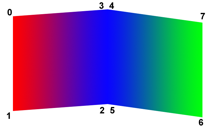
The IndexedQuadSet node represents a 3D shape composed of a collection of individual quadrilaterals (quads) as depicted in Figure 32.1. IndexedQuadSet uses the indices in its index field to specify the vertices of each quad from the coord field. Each quad is formed from a set of four vertices of the X3DCoordinateNode node identified by four consecutive indices from the index field If the index field does not contain a multiple of four coordinate values, the remaining vertices shall be ignored.
The IndexedQuadSet node is specified in the local coordinate system and is affected by the transformations of its ancestors. Descriptions of the color, coord, normal, and texCoord fields are provided in the X3DColorNode, X3DCoordinateNode, X3DNormalNode, and X3DTextureCoordinateNode nodes, respectively. If values are provided for the color, normal and texCoord fields, the values are applied in the same manner as the values from the coord field and there shall be at least as many values as are present in the coord field. The value of the colorPerVertex field is ignored and always treated as TRUE. If the normal field is not supplied, normals shall be generated as follows:
The solid field determines whether the IndexedQuadSet is visible when viewed from the inside. 11.2.3 Common geometry fields provides a complete description of the solid field.
QuadSet : X3DComposedGeometryNode {
  MFNode  [in,out] attrib          []   [X3DVertexAttributeNode]
  SFNode  [in,out] color           NULL [X3DColorNode]
  SFNode  [in,out] coord           NULL [X3DCoordinateNode]
  SFNode  [in,out] fogCoord        NULL [FogCoordinate]
  SFNode  [in,out] metadata        NULL [X3DMetadataObject]
  SFNode  [in,out] normal          NULL [X3DNormalNode]
  SFNode  [in,out] texCoord        NULL [X3DTextureCoordinateNode]
  SFBool  []       ccw             TRUE
  SFBool  []       colorPerVertex  TRUE
  SFBool  []       normalPerVertex TRUE
  SFBool  []       solid           TRUE
}
The QuadSet node represents a 3D shape that represents a collection of individual planar quadrilaterals.
The coord field contains an X3DCoordinateNode node that defines the 3D vertices that define the quad. Each quad is formed from a consecutive set of four vertices of the coordinate node. If the coordinate node does not contain a multiple of four coordinate values, the remaining vertices shall be ignored.
Figure 32.1 depicts a QuadSet node with two quads. The ordering of the vertices is also shown.
The QuadSet node is specified in the local coordinate system and is affected by the transformations of its ancestors. Descriptions of the color, coord, normal, and texCoord fields are provided in the X3DColorNode, X3DCoordinateNode, X3DNormalNode, and X3DTextureCoordinateNode nodes, respectively. If values are provided for the color, normal, and texCoord fields, there shall be at least as many values as are present in the coord field. The value of the colorPerVertex field is ignored and always treated as TRUE. If the normal field is not supplied, the normal shall be generated as perpendicular to the face for either version of normalPerVertex.
The solid field determines whether the QuadSet is visible when viewed from the inside. 11.2.3 Common geometry fields provides a complete description of the solid field.
The CADGeometry component provides two levels of support as specified in Table 32.2. Level 1 provides quad support. Level 2 adds support to describe product structure and layers.
Table 32.2 — CADGeometry component support levels
| Level | Prerequisites | Nodes/Features | Support |
|---|---|---|---|
| 1 | Core 1 Grouping 1 Rendering 1 Shape 1 |
||
| IndexedQuadSet | All fields fully supported. | ||
| QuadSet | All fields fully supported. | ||
| 2 | Core 1 Grouping 1 Rendering 1 Shape 1 |
||
| CADAssembly | All fields fully supported. | ||
| CADFace | All fields fully supported. | ||
| CADLayer | All fields fully supported. | ||
| CADPart | All fields fully supported. |
![]()