Extensible 3D (X3D)
Part 1: Architecture and base components
18 Texturing component
The name of this component is "Texturing". This name shall be used when referring to this component in the COMPONENT statement (see 7.2.5.4 Component statement).
This clause describes the Texturing component of this part of ISO/IEC 19775. This includes how textures are specified and how they are positioned on the subject geometry. Table 18.1 provides links to the major topics in this clause.
Node types specifying texture maps include Background, ImageTexture, MovieTexture, MultiTexture, PixelTexture, descendants of X3DEnvironmentTextureNode, descendants of X3DTexture3DNode. Texture maps are 2D or 3D or cubemap images that contain an array of colour values describing the texture.
Depending on the number of channels, the following texture types are possible:
Note that image formats specify alpha (i.e., opacity), not transparency (where alpha = 1 − transparency).
See 17.2.2.2 Texture sampling for a description of how the various texture types are applied.
The textures described in this component, "Texturing", only support two-dimensional map formats. See 33 Texturing3D component for a description of the use of 3D textures and 34 Cube map environmental texture component for a description of the use of cube map textures.
Texture nodes that require support for the PNG (see [I15948]) image format shall interpret the PNG pixel formats in the following way:
If the image specifies colours as indexed-colour (i.e., palettes or colourmaps), the following semantics shall be used (where `greyscale' refers to a palette entry with equal red, green, and blue values):
Texture nodes that require support for JPEG files (see [JPEG]) shall interpret JPEG files as follows:
Texture nodes that support MPEG files (see ISO/IEC 11172-1]) shall treat MPEG files as full RGB textures.
Texture nodes that recommend support for GIF files (see [GIF]) shall follow the applicable semantics described above for the PNG format.
Texture nodes that recommend support for Joint Photographic Experts Group (JPEG) 2000, Geographic Tagged Image File Format (GeoTIFF), National Imagery Transmission Format (NITF) or Basic Image Interchange Format (BIIF) formats shall follow the applicable semantics described above for the PNG format.
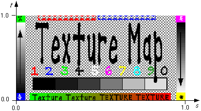
Texture maps are defined in a 2D coordinate system (s, t) that ranges from [0.0, 1.0] in both directions. The bottom edge of the image corresponds to the S-axis of the texture map, and left edge of the image corresponds to the T-axis of the texture map. The lower-left pixel of the image corresponds to s=0, t=0, and the top-right pixel of the image corresponds to s=1, t=1. Texture maps may be viewed as two dimensional colour functions that, given an (s, t) coordinate, return a colour value colour(s, t). These relationships are depicted in Figure 18.1.
The texture map nodes ImageTexture, MovieTexture, and PixelTexture contain two fields, repeatS and repeatT, that specify how the texture wraps in the S and T directions. If repeatS is TRUE (the default), the texture map is repeated outside the [0.0, 1.0] texture coordinate range in the S direction so that it fills the shape. If repeatS is FALSE, the texture coordinates are clamped in the S direction to lie within the [0.0, 1.0] range. The repeatT field is analogous to the repeatS field.
Textures nodes with a textureProperties field allow fined grained control of the texture setup including further modes for handling clamping and repeating texture coordinates and specifying how a texture should be filtered. Texture nodes with a provided TextureProperties node shall ignore the settings of repeatS and repeatT and shall use the provided values in the boundaryMode fields.
Each vertex-based geometry node (e.g., IndexedFaceSet and ElevationGrid) uses a set of 2D texture coordinates that map textures to vertices. Texture coordinates for geometry nodes are specified using the TextureCoordinate and TextureCoordinateGenerator nodes. Texture map values (ImageTexture, MovieTexture, and PixelTexture) range from [0.0, 1.0] along the S-axis and T-axis. However, texture coordinate values may be in the range (−∞,∞). Texture coordinates identify a location (and thus a colour value) in the texture map. The horizontal coordinate s is specified first, followed by the vertical coordinate t.
If the texture map is repeated in a given direction (S-axis or T-axis), a texture coordinate C (s or t) is mapped into a texture map that has N pixels in the given direction as follows:
Texture map location = (C − floor(C)) × N
If the texture map is not repeated, the texture coordinates are clamped to the 0.0 to 1.0 range as follows:
    Texture map location = N,     if C > 1.0,
                         = 0.0,   if C < 0.0,
                         = C × N, if 0.0 ≤ C ≤ 1.0.
Texture coordinates may be transformed (scaled, rotated, translated) by supplying a TextureTransform node as a component of the texture's containing Appearance node.
Details on repeating textures are specific to texture map node types described in ImageTexture, MovieTexture, and PixelTexture.
Multiple textures may be applied to a single geometry node and blended according to a predefined set of operations. This enables a variety of visual effects that include light mapping and environment mapping. Multiple textures may be applied using multi-stage or multi-pass techniques, depending upon the available hardware. The number of textures to be blended may have a significant impact on performance, depending upon the available hardware.
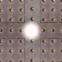
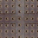
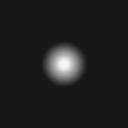
Figure 18.2 depicts an example of light mapping, simulating a pre-lit object. Texture 2 is added on top of texture 1.
Multitexturing is accomplished using the MultiTexture, MultiTextureCoordinate, and MultiTextureTransform nodes. MultiTexture specifies a grouping of single textures and texture transformations. MultiTextureCoordinate specifies a grouping of texture coordinates to be used with the associated textures. MultiTextureTransform specifies a grouping of texture transforms to be used with the associated textures.
Table 18.2 compares the usage of single texture and multitexture attributes within Appearance and geometry nodes.
Table 18.2: Comparison of single texture and multitexture attributes
| Texture Node appearance.texture | Texture Transform | Texture coordinate geometry.texCoord | Texture mode |
|---|---|---|---|
| ImageTexture { ...} |
appearance.textureTransform |
TextureCoordinate { coord [ ] } | implicit in lighting model: ["REPLACE" "MODULATE"] |
| MultiTexture { texture [ ImageTexture { ...} ImageTexture { ...} ]} |
MultiTexture { textureTransform [ TextureTransform { ...} TextureTransform { ...} ]} |
MultiTextureCoordinate { coord [ TextureCoordinate { coord [ ] }TextureCoordinate { coord [ ] } ]} |
MultiTexture { mode [ "MODULATE" "MODULATE" ]} |
If a programmable shader is defined for the Appearance node containing textures, texture mapping shall be disabled. Textures defined shall be considered as sources of input and/or output for a programmable shader. See 31.2.2.5 Per-object attributes for details on how to map textures to shader program inputs.
X3DSingleTextureCoordinateNode : X3DTextureCoordinateNode {
  SFString [in,out] mapping  ""
  SFNode   [in,out] metadata NULL [X3DMetadataObject]
}
This abstract node type is the base type for all texture coordinate nodes which specify texture coordinates for a single texture. See 12.2.4 Texture mapping specified in material nodes for a description how it interacts with texture specification inside materials.
This abstract type applies to all texture coordinate nodes except MultiTextureCoordinate.
X3DSingleTextureNode : X3DTextureNode {
  SFString [in,out] description       ""
  SFNode   [in,out] metadata          NULL [X3DMetadataObject]
  SFNode   []       textureProperties NULL [TextureProperties]
}
This abstract node type is the base type for all texture node types that define a single texture. A single texture can be used to influence a parameter of various material nodes in the Shape component, and it can be a child of MultiTexture.
This abstract type applies to all texture nodes except MultiTexture.
The textureProperties field allows fine control over a texture's application, as described in 18.2.3 Texture coordinates.
X3DSingleTextureTransformNode : X3DTextureTransformNode {
  SFString [in,out] mapping  ""
  SFNode   [in,out] metadata NULL [X3DMetadataObject]
}
This abstract node type is the base type for all texture transform nodes which specify texture coordinate transformation for a single texture. See 12.2.4 Texture mapping specified in material nodes for a description how it interacts with texture specification inside materials.
This abstract type applies to all texture transformation nodes except MultiTextureTransform.
X3DTexture2DNode : X3DSingleTextureNode {

  SFString [in,out] description       ""
  SFNode   [in,out] metadata          NULL [X3DMetadataObject]
  SFBool   []       repeatS           TRUE
  SFBool   []       repeatT           TRUE
  SFNode   []       textureProperties NULL [TextureProperties]
}
This abstract node type is the base type for all node types which specify 2D sources for texture images.
X3DTextureCoordinateNode : X3DGeometricPropertyNode {
  SFNode [in,out] metadata NULL [X3DMetadataObject]
}
This abstract node type is the base type for all node types which specify texture coordinates. It adds a new geometric property node type to those specified in 11 Rendering component.
X3DTextureNode : X3DAppearanceChildNode {
  SFString [in,out] description ""
  SFNode   [in,out] metadata    NULL [X3DMetadataObject]
}
This abstract node type is the base type for all node types which specify sources for texture images.
The description field provides textual information about the image data.
X3DTextureTransformNode : X3DAppearanceChildNode {
  SFNode [in,out] metadata NULL [X3DMetadataObject]
}
This abstract node type is the base type for all node types which specify a transformation of texture coordinates.
ImageTexture : X3DTexture2DNode, X3DUrlObject {
  SFTime   [in,out] autoRefresh          0.0  [0,∞)
  SFTime   [in,out] autoRefreshTimeLimit 3600.0  [0,∞)
  SFString [in,out] description          ""
  SFBool   [in,out] load                 TRUE
  SFNode   [in,out] metadata             NULL [X3DMetadataObject]

  MFString [in,out] url                  []   [URI]
  SFBool   []       repeatS              TRUE
  SFBool   []       repeatT              TRUE
  SFNode   []       textureProperties    NULL [TextureProperties]
}
The ImageTexture node defines a texture map by specifying an image file and general parameters for mapping to geometry.
The texture is read from the URL specified by the url field. When the url field contains no values ([]), texturing is disabled. X3D browsers shall support the JPEG (see 2. [JPEG]) and PNG (see ISO/IEC 15948) image file formats. In addition, X3D browsers may support other image formats (EXAMPLE CGM, ISO/IEC 8632) that can be rendered into a 2D image. Support for the GIF format (see [GIF]) is also recommended (including transparency). Details on the url field can be found in 9.2.1 URLs, URNs and URIs.
See 18.2 Concepts, for a general description of texture maps.
See 17 Lighting component for a description of lighting equations and the interaction between textures, materials, and geometry appearance.
MovieTexture : X3DTexture2DNode, X3DSoundSourceNode, X3DUrlObject {
  SFTime   [in,out] autoRefresh          0.0    [0,∞)
  SFTime   [in,out] autoRefreshTimeLimit 3600.0 [0,∞)
  SFString [in,out] description          ""
  SFBool   [in,out] enabled              TRUE
  SFInt32  [in,out] gain                 1      [-∞,∞)
  SFBool   [in,out] load                 TRUE
  SFBool   [in,out] loop                 FALSE
  SFNode   [in,out] metadata             NULL   [X3DMetadataObject]
  SFTime   [in,out] pauseTime            0      (-∞,∞)
  SFFloat  [in,out] pitch                1.0    (0,∞)
  SFTime   [in,out] resumeTime           0      (-∞,∞)
  SFFloat  [in,out] speed                1.0    (-∞,∞)
  SFTime   [in,out] startTime            0      (-∞,∞)
  SFTime   [in,out] stopTime             0      (-∞,∞)
  MFString [in,out] url                  []     [URI]
  SFTime   [out]    duration_changed
  SFTime   [out]    elapsedTime
  SFBool   [out]    isActive
  SFBool   [out]    isPaused
  SFBool   []       repeatS              TRUE
  SFBool   []       repeatT              TRUE
  SFNode   []       textureProperties    NULL   [TextureProperties]
}
The MovieTexture node defines a time dependent texture map (contained in a movie file) and parameters for controlling the movie and the texture mapping. A MovieTexture node can also be used as the source of sound data for a Sound node. In this special case, the MovieTexture node is not used for rendering.
The url field that defines the movie data shall support MPEG1-Systems (audio and video) or MPEG1-Video (video-only) movie file formats as defined in ISO/IEC 11172-1. Details on the url field can be found in 9.2.1 URLs, URNs and URIs.
MovieTexture nodes can be referenced by an Appearance node's texture field (as a movie texture) and by a Sound node's source field (as an audio source only).
As soon as the movie is loaded, a duration_changed field is sent. This indicates the duration of the movie in seconds. This field value can be read (for instance, by a Script node) to determine the duration of a movie. A value of "-1" implies the movie has not yet loaded or the value is unavailable for some reason.
The cycle of a MovieTexture node is the length of time in seconds for one playing of the movie at the specified speed.
The pitch field specifies a multiplier for the rate at which sampled sound is played. Values for the pitch field shall be greater than zero. Changing the pitch field affects both the pitch and playback speed of a sound. A set_pitch event to an active MovieTexture node is ignored and no pitch_changed field is generated. If pitch is set to 2.0, the sound shall be played one octave higher than normal and played twice as fast. For a sampled sound, the pitch field alters the sampling rate at which the sound is played. The proper implementation of pitch control for MIDI (or other note sequence sound clips) is to multiply the tempo of the playback by the pitch value and adjust the MIDI Coarse Tune and Fine Tune controls to achieve the proper pitch change.
A duration_changed event is sent whenever there is a new value for the "normal" duration of the clip. Typically, this will only occur when the current url in use changes and the sound data has been loaded, indicating that the clip is playing a different sound source. The duration is the length of time in seconds for one cycle of the audio for a pitch set to 1.0. Changing the pitch field will not trigger a duration_changed event. A duration value of "−1" implies that the sound data has not yet loaded or the value is unavailable for some reason. A duration_changed event shall be generated if the MovieTexture node is loaded when the X3D file is read or the MovieTexture node is added to the scene graph.
The speed field indicates how fast the movie shall be played. A speed of 2 indicates the movie plays twice as fast. The duration_changed output is not affected by the speed field. set_speed events are ignored while the movie is playing. A negative speed implies that the movie will play backwards.
If a MovieTexture node is inactive when the movie is first loaded, frame 0 of the movie texture is displayed if speed is non-negative or the last frame of the movie texture is shown if speed is negative (see 8.2.4 Time-dependent nodes). A MovieTexture node shall display frame 0 if speed = 0. For positive values of speed, an active MovieTexture node displays the frame at movie time t as follows (i.e., in the movie's local time system with frame 0 at time 0 with speed = 1):
t = (now − startTime) modulo (duration/speed)
If speed is negative, the MovieTexture node displays the frame at movie time:
t = duration - ((now - startTime) modulo |duration/speed|)
When a MovieTexture node becomes inactive, the frame corresponding to the time at which the MovieTexture became inactive will remain as the texture.
See 18.2 Concepts, for a general description of texture maps.
17 Lighting component contains details on lighting equations and the interaction between textures, materials, and geometries.
MultiTexture : X3DTextureNode {
  SFFloat  [in,out] alpha       1     [0,1]
  SFColor  [in,out] color       1 1 1 [0,1]
  SFString [in,out] description ""
  MFString [in,out] function    []
  SFNode   [in,out] metadata    NULL  [X3DMetadataObject]
  MFString [in,out] mode        []
  MFString [in,out] source      []
  MFNode   [in,out] texture     []    [X3DSingleTextureNode]
}
The MultiTexture node specifies the application of several individual textures to a 3D object to achieve a more complex visual effect. MultiTexture can be used as a value for the texture field in an Appearance node.
The texture field contains a list of texture nodes (e.g., ImageTexture, PixelTexture, and MovieTexture). The texture field may not contain another MultiTexture node.
The color and alpha fields define base RGB and alpha values for SELECT mode operations.
The mode field controls the type of blending operation. The available modes mode values are shown in Table 18.3 and include MODULATE for a lit Appearance, REPLACE for an unlit Appearance, and several variations of the two. The value chosen for the mode field may also specify the blending mode for the alpha channel.
EXAMPLE The mode value '"MODULATE","REPLACE"' specifies Color = (Arg1.color × Arg2.color, Arg1.alpha).
The number of used texture stages is determined by the length of the texture field. If there are fewer mode values, the default mode is "MODULATE".
Table 18.3 lists possible multitexture modes.
Table 18.3 — Multitexture values for mode field modes
| mode value MODE | Description |
|---|---|
| "MODULATE" (default) | Multiply texture color with current color Arg1 × Arg2 |
| "REPLACE" | Replace current color Arg2 |
| "MODULATE2X" | Multiply the components of the arguments, and shift the products to the left 1 bit (effectively multiplying them by 2) for brightening. |
| "MODULATE4X" | Multiply the components of the arguments, and shift the products to the left 2 bits (effectively multiplying them by 4) for brightening. |
| "ADD" | Add the components of the arguments Arg1 + Arg2 |
| "ADDSIGNED" | Add the components of the arguments with a -0.5 bias, making the effective range of values from −0.5 through 0.5. |
| "ADDSIGNED2X" | Add the components of the arguments with a -0.5 bias, and shift the products to the left 1 bit. |
| "SUBTRACT" | Subtract the components of the second argument from those of the
first argument. Arg1 − Arg2 |
| "ADDSMOOTH" | Add the first and second arguments, then subtract their product from
the sum. Arg1 + Arg2 − Arg1 × Arg2 = Arg1 + (1 − Arg1) × Arg2 |
| "BLENDDIFFUSEALPHA" | Linearly blend this texture stage, using the interpolated alpha from
each vertex. Arg1 × (Alpha) + Arg2 × (1 − Alpha) |
| "BLENDTEXTUREALPHA" | Linearly blend this texture stage, using the alpha from this stage's
texture. Arg1 × (Alpha) + Arg2 × (1 − Alpha) |
| "BLENDFACTORALPHA" | Linearly blend this texture stage, using the alpha factor from the
MultiTexture node. Arg1 × (Alpha) + Arg2 × (1 − Alpha) |
| "BLENDCURRENTALPHA" | Linearly blend this texture stage, using the alpha taken from the
previous texture stage. Arg1 × (Alpha) + Arg2 × (1 − Alpha) |
| "MODULATEALPHA_ADDCOLOR" | Modulate the color of the second argument, using the alpha of the
first argument; then add the result to argument one. Arg1.RGB + Arg1.A × Arg2.RGB |
| "MODULATEINVALPHA_ADDCOLOR" | Similar to MODULATEALPHA_ADDCOLOR, but use the inverse of the alpha
of the first argument. (1 − Arg1.A) × Arg2.RGB + Arg1.RGB |
|
"MODULATEINVCOLOR_ADDALPHA" |
Similar to MODULATECOLOR_ADDALPHA, but use the inverse of the color of
the first argument. (1 − Arg1.RGB) × Arg2.RGB + Arg1.A |
| "OFF" | Turn off the texture unit |
| "SELECTARG1" | Use color argument 1 Arg1 |
| "SELECTARG2" | Use color argument 2 Arg2 |
| "DOTPRODUCT3" | Modulate the components of each argument (as signed components),
add their products, then replicate the sum to all color channels,
including alpha. This can do either diffuse or specular bump mapping with correct input. Performs the function (Arg1.R × Arg2.R + Arg1.G × Arg2.G + Arg1.B × Arg2.B) where each component has been scaled and offset to make it signed. The result is replicated into all four (including alpha) channels. |
The source field determines the colour source for the second argument. Table 18.4 lists valid values for the source field. Typically, there are the same number of source field values as textures. Otherwise, the default source field value is used.
Table 18.4 — MultiTexture values for source field Values for the source field
| source value MODE | Description |
|---|---|
| "" (empty string) (default) | The second argument color (ARG2) is the color from the previous rendering stage (DIFFUSE for first stage). |
| "DIFFUSE" | The texture argument is the diffuse color interpolated from vertex components during Gouraud shading. |
| "SPECULAR" | The texture argument is the specular color interpolated from vertex components during Gouraud shading. |
| "FACTOR" | The texture argument is the factor from MultiTexture node color and alpha fields. |
The function field defines an optional function to be applied to the argument after the mode has been evaluated. Table 18.5 lists valid values for the function field. Typically, there are the same number of function field values as textures. Otherwise, the default function field value is used.
Table 18.5 — MultiTexture values for function field Values for the function field
| function value Operator | Description |
|---|---|
| "" (empty string) (default) | No function is applied. |
| "COMPLEMENT" | Invert the argument so that, if the result of the argument were referred to by the variable x, the value would be 1.0 minus x. |
| "ALPHAREPLICATE" | Replicate the alpha information to all color channels before the operation completes. |
MultiTextureCoordinate : X3DTextureCoordinateNode {
  SFNode [in,out] metadata NULL [X3DMetadataObject]
  MFNode [in,out] texCoord NULL [X3DSingleTextureCoordinateNode]
}
MultiTextureCoordinate supplies multiple texture coordinates per vertex. This node can be used to set the texture coordinates for the different texture channels. It can be used to provide texture coordinates:
For the texture specified in the Appearance.texture field. This includes a MultiTexture node. In this case the order of the texture coordinates must match the order of texture nodes within the MultiTexture.texture list.
For any texture specified within material nodes using fields like Material.diffuseTexture, PhysicalMaterial.baseTexture. In this case, the mapping field of the child X3DSingleTextureCoordinateNode node must correspond to the appropriate xxxTextureMapping value in the material. See 12.2.4 Texture mapping specified in material nodes for details.
Each entry in the texCoord field may contain a TextureCoordinate, TextureCoordinateGenerator or other X3DSingleTextureCoordinateNode descendant node.
Example:
Shape {
  appearance Appearance {
    texture MultiTexture {
      mode [ "MODULATE" "MODULATE" ]
      texture [
        ImageTexture { url "brick.jpg")
        ImageTexture { repeatS FALSE repeatT FALSE url "light_gray.png"}
      ]
    }
  }
  geometry IndexedFaceSet {
      ...
    texCoord MultiTextureCoordinate {
      texCoord [
        TextureCoordinate { ... }
        TextureCoordinate { ... }
      ]
    }
  }
}
Using a MultiTextureCoordinate with exactly one child is always equivalent to using this child directly. That is, these two constructs (in X3D classic encoding) are exactly equivalent for the purpose of texture coordinate determination:
IndexedFaceSet {
  texCoord TextureCoordinate {
    point [ 0 0, 1 1 ]
  }
}
IndexedFaceSet {
texCoord MultiTextureCoordinate {
texCoord [
TextureCoordinate {
point [ 0 0, 1 1 ]
}
]
}
}When the MultiTexture node is used in Appearance.texture field, and there is not enough texture coordinates in the MultiTextureCoordinate, texture coordinates for the last channel are replicated along the other channels.
MultiTextureTransform : X3DTextureTransformNode {
  SFNode [in,out] metadata         NULL [X3DMetadataObject]
  MFNode [in,out] textureTransform NULL [X3DSingleTextureTransformNode]
}
MultiTextureTransform supplies multiple texture transforms per appearance. This node can be used to set the texture transform for each of the different texture channels. It can be used to transform texture coordinates:
For the texture specified in the Appearance.texture field. This includes a MultiTexture node. In this case the order of the texture transformations must match the order of texture nodes within the MultiTexture.texture list.
For any texture specified within material nodes using fields like Material.diffuseTexture, PhysicalMaterial.baseTexture. In this case, the mapping field of the child X3DSingleTextureTransformNode node must correspond to the appropriate xxxTextureMapping value in the material. See 12.2.4 Texture mapping specified in material nodes for details.
Each entry in the textureTransform field shall contain an X3DSingleTextureTransformNode or NULL.
Example:
Shape {
  appearance Appearance {
    texture MultiTexture {
      mode [ "MODULATE" "MODULATE" ]
      texture [
        ImageTexture { url "brick.jpg")
        ImageTexture { repeatS FALSE repeatT FALSE url "light_gray.png"}
      ]
    }

    textureTransform MultiTextureTransform {
      textureTransform [
	TextureTransform {}
	TextureTransform { scale 0.5 0.5 }
      ]
    }
  }
}
Note that we treat a MultiTextureTransform with a single child always the same as using this child directly. That, is these two constructs are equivalent, for the purpose of texture transformation determination:
Appearance {
  textureTransform TextureTransform {
    scale 10 10
  }
}
Appearance {
textureTransform MultiTextureTransform {
textureTransform [
TextureTransform {
scale 10 10
}
]
}
}
When the MultiTexture node is used in Appearance.texture field, and there is not enough texture coordinates in the MultiTextureTransform, identity matrices (no transformation) shall be used for all remaining channels.
PixelTexture : X3DTexture2DNode {
  SFString [in,out] description       ""
  SFImage  [in,out] image             0 0 0
  SFNode   [in,out] metadata          NULL  [X3DMetadataObject]
  SFBool   []       repeatS           TRUE
  SFBool   []       repeatT           TRUE
  SFNode   []       textureProperties NULL  [TextureProperties]
}
The PixelTexture node defines a 2D image-based texture map as an explicit array of pixel values (image field) and parameters controlling tiling repetition of the texture onto geometry.
The repeatS and repeatT fields specify how the texture wraps in the S and T directions. If repeatS is TRUE (the default), the texture map is repeated outside the 0-to-1 texture coordinate range in the S direction so that it fills the shape. If repeatS is FALSE, the texture coordinates are clamped in the S direction to lie within the 0.0 to 1.0 range. The repeatT field is analogous to the repeatS field.
See 18.2 Concepts, for a general description of texture maps.
See 17 Lighting component for a description of how the texture values interact with the appearance of the geometry. 5.7 SFImage and MFImage describes the specification of an image.
TextureCoordinate : X3DSingleTextureCoordinateNode {
  SFString [in,out] mapping  ""
  SFNode   [in,out] metadata NULL [X3DMetadataObject]
  MFVec2f  [in,out] point    []   (-∞,∞)
}
The TextureCoordinate node is a geometry property node that specifies a set of 2D texture coordinates used by vertex-based geometry nodes (EXAMPLE IndexedFaceSet and ElevationGrid) to map textures to vertices.
TextureCoordinateGenerator : X3DSingleTextureCoordinateNode {
  SFString [in,out] mapping   ""
  SFNode   [in,out] metadata  NULL     [X3DMetadataObject]
  SFString [in,out] mode      "SPHERE" (see Table 18.6)
  MFFloat  [in,out] parameter []       (see Table 18.6)
}
TextureCoordinateGenerator supports the automatic generation of texture coordinates for geometric shapes.
This node can be used to set the texture coordinates for a node with a texCoord field.
The mode field describes the algorithm used to compute texture coordinates, as depicted in Table 18.6.
Table 18.6 — Texture coordinate generation modes
| mode value Mode | Description |
|---|---|
| "SPHERE" | Creates texture coordinates for a spherical environment or "chrome"
mapping based on the vertex normals transformed to camera space. u = Nx/2 + 0.5 v = Ny/2 + 0.5 where u and v are the texture coordinates being computed, and Nx and Ny are the x and y components of the camera-space vertex normal. If the normal has a positive x component, the normal points to the right, and the u coordinate is adjusted to address the texture appropriately. Likewise for the v coordinate: positive y indicates that the normal points up. The opposite is of course true for negative values in each component. If the normal points directly at the camera, the resulting coordinates should receive no distortion. The +0.5 bias to both coordinates places the point of zero-distortion at the center of the sphere map, and a vertex normal of (0, 0, z) addresses this point. Note that this formula does not take account for the z component of the normal. |
| "CAMERASPACENORMAL" | Use the vertex normal, transformed to camera space, as input texture coordinates, resulting coordinates are in −1 to 1 range. |
| "CAMERASPACEPOSITION" | Use the vertex position, transformed to camera space, as input texture coordinates |
| "CAMERASPACEREFLECTIONVECTOR" | Use the reflection vector, transformed to camera space, as input
texture coordinates. The reflection vector is computed from the input
vertex position and normal vector. R=2 × DotProd(E,N) × N − E; In the preceding formula, R is the reflection vector being computed, E is the normalized position-to-eye vector, and N is the camera-space vertex normal. Resulting coordinates are in −1 to 1 range. |
| "SPHERE-LOCAL" | Sphere mapping but in local coordinates |
| "COORD" | use vertex coordinates |
| "COORD-EYE" | use vertex coordinates transformed to camera space |
| "NOISE" | computed by applying Perlin solid noise function on vertex coordinates, parameter contains scale and translation [scale.x scale.y scale.z translation.x translation.y translation.z] |
| "NOISE-EYE" | same as above but transform vertex coordinates to camera space first |
| "SPHERE-REFLECT" | similar to "CAMERASPACEREFLECTIONVECTOR"
with optional index of refraction, parameter[0]
contains index of refraction
Resulting coordinates are in −1 to 1 range. |
| "SPHERE-REFLECT-LOCAL" | Similar to "SPHERE-REFLECT", parameter[0]
contains index of refraction, parameter[1 to 3] the eye point in local
coordinates. By animating parameter [1 to 3] the reflection changes
with respect to the point. Resulting coordinates are in −1 to 1 range. |
Some modes may be hardware accelerated. Some modes are view dependent.
TextureProperties : X3DNode
  SFFloat     [in,out] anisotropicDegree   1.0       [1,∞)
  SFColorRGBA [in,out] borderColor         0 0 0 0   [0,1] (deprecated v4.0)
  SFInt32     [in,out] borderWidth         0         [0,1] (deprecated v4.0)
  SFString    [in,out] boundaryModeR       "REPEAT"  (see Table 18.7)
  SFString    [in,out] boundaryModeS       "REPEAT"  (see Table 18.7)
  SFString    [in,out] boundaryModeT       "REPEAT"  (see Table 18.7)
  SFString    [in,out] magnificationFilter "FASTESTDEFAULT" (see Table 18.8)
  SFNode      [in,out] metadata            NULL      [X3DMetadataObject]
  SFString    [in,out] minificationFilter  "FASTESTDEFAULT" (see Table 18.9)
  SFString    [in,out] textureCompression  "FASTESTDEFAULT" (see Table 18.10)
  SFFloat     [in,out] texturePriority     0         [0,1]
  SFBool      []       generateMipMaps     FALSE
}
TextureProperties allows fine control over a texture's application.
This node can be used to set the texture properties for a node with a textureProperties field. A texture with a TextureProperties node will ignore the repeatS and repeatT fields on the texture.
The anisotropicDegree field describes the minimum degree of anisotropy to account for in texture filtering. A value of 1 implies no anisotropic filtering. Values above the system's maximum supported value will be clamped to the maximum allowed. X3D browsers are allowed to use higher values as deemed appropriate.
The borderColor field (deprecated v4.0) describes the color to use for border pixels.
The borderWidth field (deprecated v4.0) describes the number of pixels to use for a texture border.
The boundaryModeS field describes the way S texture coordinate boundaries are handled, as depicted in Table 18.7.
The boundaryModeT field describes the way T texture coordinate boundaries are handled, as depicted in Table 18.7.
The boundaryModeR field describes the way R texture coordinate boundaries are handled, as depicted in Table 18.7. This field only applies to three dimensional textures and shall be ignored by other texture types.
The magnificationFilter field describes the way textures are filtered when the image is smaller than the screen space representation. Valid values are depicted in Table 18.8.
The minificationFilter field describes the way textures are filtered when the image is larger than the screen space representation. Valid values are depicted in Table 18.9. Modes with MIPMAP in the name require mipmaps. If mipmaps are not provided, the mode shall pick the corresponding non-mipmapped mode (e.g., AVG_PIXEL_NEAREST_MIPMAP becomes AVG_PIXEL).
The texturePriority field describes the texture residence priority for allocating texture memory. Zero indicates the lowest priority and 1 indicates the highest priority. Values are clamped to the range [0,1].
The textureCompression field specifies the preferred image compression method to be used during rendering. Valid values are depicted in Table 18.10.
The generateMipMaps field describes whether mipmaps should be generated for the texture. Mipmaps are required for filtering modes with MIPMAP in their value.
Table 18.7 — Texture boundary modes
| boundary mode value Mode | Description |
|---|---|
| "CLAMP" | Clamp texture coordinates to the range [0,1] |
| "CLAMP_TO_EDGE" | Clamp texture coordinates such that a border texel is never
sampled. Coordinates are clamped to the range [1/(2N), 1 - 1/(2N)], where N is the size of the texture in the direction of clamping. |
| "CLAMP_TO_BOUNDARY" | Clamp texture coordinates such that texture samples are border
texels for fragments whose corresponding texture coordinate is sufficiently outside the range [0,1]. Texture coordinates are clamped to the range [-1/(2N), 1 + 1/(2N)]. |
| "MIRRORED_REPEAT" | Texture coordinates are mirrored and then clamped as in CLAMP_TO_EDGE |
| "REPEAT" | Repeat a texture across the fragment. Ignore the integer part of the texture coordinates, using only the fractional part. |
Table 18.8 — Texture magnification modes
| magnificationFilter value Mode | Description |
|---|---|
| "AVG_PIXEL" | Select the weighted average of the four texture elements that are closest to the center of the pixel being textured. |
| "DEFAULT" | Select the X3D browser-specified default magnification mode. |
| "FASTEST" | Select the fastest method available. |
| "NEAREST_PIXEL" | Select the texture element that is nearest to the center of the pixel being textured. |
| "NICEST" | Select the highest quality method available. |
Table 18.9 — Texture minification modes
| minificationFilter value Mode | Description |
|---|---|
| "AVG_PIXEL" | Select the weighted average of the four texture elements that are closest to the center of the pixel being textured. |
| "AVG_PIXEL_AVG_MIPMAP" | Performs tri-linear filtering. Choose the two mipmaps that most closely match the size of the pixel being textured and use the weighted average of the four texture elements that are closest to the center of the pixel to produce a texture value from each mipmap. The final texture value is a weighted average of those two values. |
| "AVG_PIXEL_NEAREST_MIPMAP" | Choose the mipmap that most closely matches the size of the pixel being textured and use the weighted average of the four texture elements that are closest to the center of the pixel to produce a texture value. |
| "DEFAULT" | Select the X3D browser-specified default minification mode. |
| "FASTEST" | Select the fastest method available. Mipmaps shall be used, if available. |
| "NEAREST_PIXEL" | Select the texture element that is nearest to the center of the pixel being textured. |
| "NEAREST_PIXEL_AVG_MIPMAP" | Choose the two mipmaps that most closely match the size of the pixel being textured and use the texture element nearest to the center of the pixel to produce a texture value from each mipmap. The final texture value is a weighted average of those two values. |
| "NEAREST_PIXEL_NEAREST_MIPMAP" | Choose the mipmap that most closely matches the size of the pixel being textured and use the texture element nearest to the center of the pixel) to produce a texture value. |
| "NICEST" | Select the highest quality method available. Mipmaps shall be used, if available. |
Table 18.10 — Texture compression modes
| textureCompression value Mode | Description |
|---|---|
| "DEFAULT" | Select the X3D browser-specified default compression mode. |
| "FASTEST" | Select the fastest compression mode available. |
| "HIGH" | Select the compression mode with the greatest amount of compression. |
| "LOW" | Select the compression mode with the least amount of compression. |
| "MEDIUM" | Select a compression mode with a moderate amount of compression. |
| "NICEST" | Select the compression mode that produces the highest quality effect. |
TextureTransform : X3DSingleTextureTransformNode {
  SFVec2f  [in,out] center      0 0  (-∞,∞)
  SFString [in,out] mapping     ""
  SFNode   [in,out] metadata    NULL [X3DMetadataObject]
  SFFloat  [in,out] rotation    0    (-∞,∞)
  SFVec2f  [in,out] scale       1 1  (-∞,∞)
  SFVec2f  [in,out] translation 0 0  (-∞,∞)
}
The TextureTransform node defines a 2D transformation that is applied to texture coordinates (see TextureCoordinate). This node affects the way textures coordinates are applied to the geometric surface. The transformation consists of (in order):
These parameters support changes to the size, orientation, and position of textures on shapes. Note that these operations appear reversed when viewed on the surface of geometry. For example, a scale value of (2 2) will scale the texture coordinates and have the net effect of shrinking the texture size by a factor of 2 (texture coordinates are twice as large and thus cause the texture to repeat). A translation of (0.5 0.0) translates the texture coordinates +.5 units along the S-axis and has the net effect of translating the texture −0.5 along the S-axis on the geometry's surface. A rotation of π/2 of the texture coordinates results in a −π/2 rotation of the texture on the geometry.
The center field specifies a translation offset in texture coordinate space about which the rotation and scale fields are applied. The scale field specifies a scaling factor in S and T of the texture coordinates about the center point. scale values shall be in the range (−∞,∞). The rotation field specifies a rotation in angle base units of the texture coordinates about the center point after the scale has been applied. A positive rotation value makes the texture coordinates rotate counterclockwise about the centre, thereby rotating the appearance of the texture itself clockwise. The translation field specifies a translation of the texture coordinates.
In matrix transformation notation, where Tc is the untransformed texture coordinate, Tc' is the transformed texture coordinate, C (center), T (translation), R (rotation), and S (scale) are the intermediate transformation matrices,
Tc' = −C × S × R × C × T × Tc
NOTE This transformation order is the reverse of the Transform node transformation order since the texture coordinates, not the texture, are being transformed (i.e., the texture coordinate system).
The Texturing component provides three levels of support as specified in Table 18.7.
Table 18.11 — Texturing component support levels
| Level | Prerequisites | Nodes/Features | Support |
|---|---|---|---|
| 1 | Core 1 Grouping 1 Shape 1 Rendering 1 |
||
| X3DSingleTextureCoordinateNode (abstract) | n/a | ||
| X3DSingleTextureNode (abstract) | n/a | ||
| X3DSingleTextureTransformNode (abstract) | n/a | ||
| X3DTextureCoordinateNode (abstract) | n/a | ||
| X3DTextureNode (abstract) | n/a | ||
| X3DTexture2DNode (abstract) | n/a | ||
| X3DTextureTransformNode (abstract) | n/a | ||
| ImageTexture | All fields fully supported. | ||
| PixelTexture | All fields fully supported. | ||
| TextureCoordinate | All fields fully supported. | ||
| TextureTransform | All field fully supported. | ||
| 2 | Core 1 Grouping 1 Shape 1 Rendering 1 |
||
| All Level 1 Texturing nodes | All fields as supported in Level 1. | ||
| MultiTextureCoordinate | All fields fully supported. | ||
| MultiTextureTransform | All fields fully supported. | ||
| TextureCoordinateGenerator | All fields fully supported. | ||
| TextureProperties | All fields fully supported. | ||
| 3 | Core 1 Grouping 1 Shape 1 Rendering 1 |
||
| All Level 2 Texturing nodes | All fields as supported in Level 2. | ||
| MultiTexture | All fields fully supported. | ||
| 4 | Core 1 Grouping 1 Shape 1 Rendering 1 |
||
| All Level 3 Texturing nodes | All fields as supported in Level 3. | ||
| MovieTexture | All fields fully supported. |
![]()
 + Lightmap
 = Result