Extensible 3D (X3D)
Part 1: Architecture and base components
16 Sound component
The name of this component is "Sound". This name shall be used when referring to this component in the COMPONENT statement (see 7.2.5.4 Component statement).
This clause describes the Sound component of this part of ISO/IEC 19775. This includes how sound is delivered to an X3D world as well as how sounds are accessed. Table 16.1 provides links to the major topics in this clause.
If the browser does not have the resources to play all of the currently active sounds, it is recommended that the browser sort the active sounds into an ordered list using the following sort keys in the order specified:
where priority is the priority field of the Sound node, now represents the current time, startTime is the startTime field of the audio source node specified in the source field, and "intensity attenuation" refers to the intensity multiplier derived from the linear decibel attenuation ramp between inner and outer ellipsoids.
It is important that sort key 2 be used for the high priority (event and cue) sounds so that new cues are heard even when the browser is "full" of currently active high priority sounds. Sort key 2 should not be used for normal priority sounds, so selection among them is based on sort key 3 (intensity at the location of the viewer).
The browser shall play as many sounds from the beginning of this sorted list as it can given available resources and allowable latency between rendering. On most systems, the resources available for MIDI streams are different from those for playing sampled sounds, thus it may be beneficial to maintain a separate list to handle MIDI data.
In order to create a linear decrease in loudness as the viewer moves from the inner to the outer ellipsoid of the sound, the attenuation must be based on a linear decibel ramp. To make the falloff consistent across browsers, the decibel ramp is to vary from 0 dB at the minimum ellipsoid to -20 dB at the outer ellipsoid. Sound nodes with an outer ellipsoid that is ten times larger than the minimum will display the inverse square intensity drop-off that approximates sound attenuation in an anechoic environment.
Browsers may support spatial localization of sounds whose spatialize
field is TRUE as well as their underlying sound
libraries will allow. Browsers shall at least support stereo panning of non-MIDI
sounds based on the angle between the viewer and the source. This angle is obtained
by projecting the Sound location (in global space) onto the XZ plane
of the viewer. Determine the angle between the Z-axis and the vector from the
viewer to the transformed location, and assign a pan value in the range
[0.0, 1.0] as depicted in Figure 16.1. Given
this pan value, left and right channel levels can be obtained using the following
equations:
leftPanFactor = 1 - pan2
rightPanFactor = 1 - (1 - pan)2
Using this technique, the loudness of the sound is modified by the intensity field value, then distance attenuation to obtain the unspatialized audio output. The values in the unspatialized audio output are then scaled by leftPanFactor and rightPanFactor to determine the final left and right output signals. The use of more sophisticated localization techniques is encouraged, but not required (see [SNDB]).
These planar gain-reduction relationships pertain to relative direction of current viewer and also any ListenerPoint nodes.
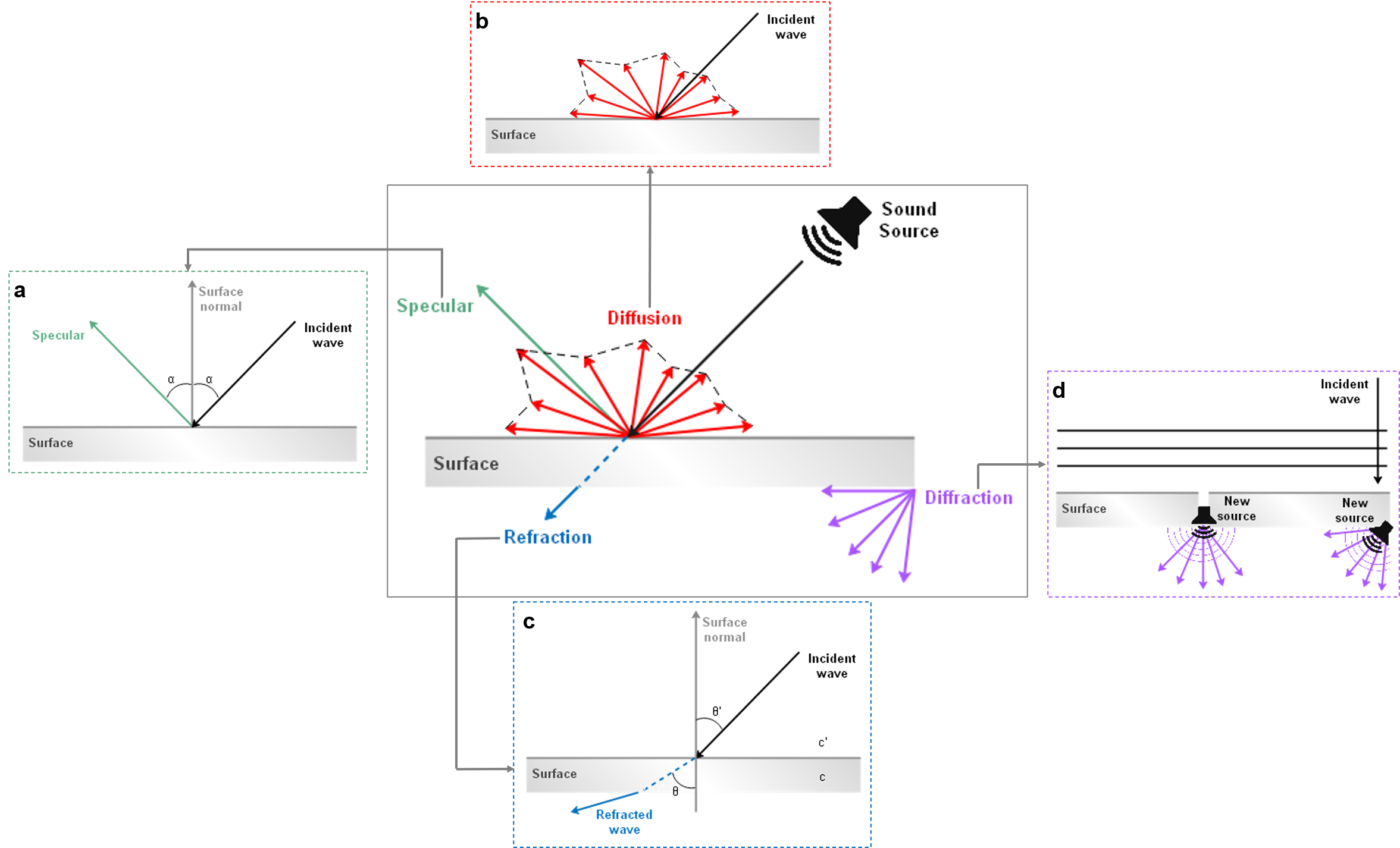
Sound-propagation techniques can be used to simulate sound waves as they travel from each source to scene listening points by taking into account the expected interactions with various objects in the scene. In other words, spatial sound rendering includes the estimation of physical effects involved in sound propagation such as surface reflection (specular, diffusion) and wave phenomena (refraction, diffraction) within a 3D scene. Figure 16.2 provides an overview of the physical models of sound propagation that are considered.
n = c'/c = sinθ'/sinθ
where c’ and c the sound speed in the two media, θ the angle of incidence and θ’ the angle of refraction.
(TODO: consider improvement or removal.) Diffraction sources are not explicitly represented in this component, and often can be handled by computational engines. Complex geometric openings may also be modeled by an audio chain including ListenerPoint and SpatialSound to emulate sophisticated diffraction propagation paths.
If a simplified geometry alternative from Collision proxy field is available, it is used preferentially by collision-detection algorithms for sound propagation, rather than descendant children of the Collision node. Such geometric simplifications can often reduce computational costs significantly without reduction in perceived audio fidelity of 3D scene acoustics. (TODO: consider need for acousticProxy field, or if Shape/Appearance/AcousticProperties is sufficient.)
Sound streams can be manipulated by a variety of sound effects. Audio graphs are a powerful mechanism for modeling the diversity of real-world and electronic modifications to sound that can occur. Close integration of sound rendering and effects with 3D models and aggregate scenes provides powerful capabilities for increased realism.
Historically a wide variety of computational libraries for sound generation and propagation have been available, often with significant differences and limitations. Sound propagation and effects processing in this component are based on design patterns found in W3C Web Audio API [W3C-WebAudio]. Design goals of that specification include supporting "the capabilities found in modern game audio engines as well as some of the mixing, processing, and filtering tasks that are found in modern desktop audio production applications." These capabilities are broad, implemented in a variety of libraries, and deployed in multiple Web browsers. The primary interfaces of W3C Web Audio API [W3C-WebAudio] necessary for creating audio graphs have corresponding X3D node support in this component.
TODO continued design, implementation and evaluation work for this component is needed to ensure that full coverage of W3C Audio API capabilities is achieved.
Descriptions follow for a number of fields that are common to multiple nodes related to sound processing.
The channelCount field is the number of channels used when up-mixing and down-mixing connections to any inputs of a node. The default value is typically 2 except for specific nodes where its value is specially determined This attribute has no effect for nodes with no inputs.
The channelCountMode field is used to determine the computedNumberOfChannels that controls how inputs to a node are to be mixed.
"max": use computedNumberOfChannels (value for channelCount is ignored)"clamped-max": use computedNumberOfChannels clamped to maximum value given by channelCount "explicit": Up-mix by filling channels until they run out then zero out remaining channels.
Down-mix by filling as many channels as possible, then dropping remaining channels. . The channelInterpretation field determines how individual channels are treated when up-mixing and down-mixing connections to any inputs to the node. The default value is "speakers". This attribute has no effect for nodes with no inputs. Allowed values include the following:
"speakers": use up-mix equations or down-mix equations. In cases where the number of channels
do not match any of these basic speaker layouts, revert to "discrete". "discrete": computedNumberOfChannels is the exact value as specified by the channelCount. The gain field is amplification applied to an input signal. TODO linear factor or decibels?
The numberOfInputs field is the number of inputs feeding into a node.
The numberOfOutputs field is the number of outputs coming out of a node.
TODO: do most or all interfaces include a gain field?
X3DSoundAnalysisNode : X3DNode {
  SFString [in,out] description  ""

  SFInt32  [in,out] channelCount          0          [0,∞)
  SFString [in,out] channelCountMode      "max"      ["max", "clamped-max", "explicit"]
  SFString [in,out] channelInterpretation "speakers" ["speakers", "discrete"]
  SFInt32  [in,out] numberOfInputs        0          [0,∞)
  SFInt32  [in,out] numberOfOutputs       0          [0,∞)
  # Mechanisms for parent-child input-output graph design remain under review
}
This is the base node type for nodes which receive real-time generated data, without any change from the input to output sound information.
TODO: if enabled FALSE, does signal pass through unmodified or is it blocked? Perhaps an additional boolean is needed for pass-through state? Modeling the 'connect' attribute and defining defaults is necessary for each case.
X3DSoundChannelNode : X3DTimeDependentNode {
  SFString [in,out] description  ""
  SFBool   [in,out] enabled      TRUE
  SFBool   [in,out] loop         FALSE
  SFNode   [in,out] metadata     NULL  [X3DMetadataObject]
  SFTime   [in,out] pauseTime    0     (-∞,∞)
  SFTime   [in,out] resumeTime   0     (-∞,∞)
  SFTime   [in,out] startTime    0     (-∞,∞)
  SFTime   [in,out] stopTime     0     (-∞,∞)
  SFTime   [out]    elapsedTime
  SFBool   [out]    isActive
  SFBool   [out]    isPaused

  SFInt32  [in,out] channelCount          0          [0,∞)
  SFString [in,out] channelCountMode      "max"      ["max", "clamped-max", "explicit"]
  SFString [in,out] channelInterpretation "speakers" ["speakers", "discrete"]
  SFInt32  [in,out] numberOfInputs        0          [0,∞)
  SFInt32  [in,out] numberOfOutputs       0          [0,∞)
  # Mechanisms for parent-child input-output graph design remain under review
}
This is the base node type for nodes that handle of channels in an audio stream, allowing them to be split or merged.
(Section moved here and adapted from AudioClip.)
The description, enabled, loop, pauseTime, resumeTime, startTime, and stopTime inputOutput fields
and the elapsedTime, isActive, and isPaused outputOnly fields, and their effects on nodes implementing this abstract node type,
are discussed in detail in
X3DTimeDependentNode and
8.2.4 Time-dependent nodes.
TODO: if enabled FALSE, does signal pass through unmodified or is it blocked? Perhaps an additional boolean is needed for pass-through state? Modeling the 'connect' attribute and defining defaults is necessary for each case.
X3DSoundDestinationNode : X3DTimeDependentNode {
  SFString [in,out] description  ""
  SFBool   [in,out] enabled      TRUE
  SFBool   [in,out] loop         FALSE
  SFNode   [in,out] metadata     NULL  [X3DMetadataObject]
  SFTime   [in,out] pauseTime    0     (-∞,∞)
  SFTime   [in,out] resumeTime   0     (-∞,∞)
  SFTime   [in,out] startTime    0     (-∞,∞)
  SFTime   [in,out] stopTime     0     (-∞,∞)
  SFTime   [out]    elapsedTime
  SFBool   [out]    isActive
  SFBool   [out]    isPaused

  SFInt32  [in,out] channelCount          0          [0,∞)
  SFString [in,out] channelCountMode      "max"      ["max", "clamped-max", "explicit"]
  SFString [in,out] channelInterpretation "speakers" ["speakers", "discrete"]
  SFInt32  [in,out] numberOfInputs        0          [0,∞)
  SFInt32  [in,out] numberOfOutputs       0          [0,∞)
  # Mechanisms for parent-child input-output graph design remain under review
}
This is the base node type for all sound destination nodes, which represent the final destination of an audio signal and are what the user can ultimately hear. Such nodes are often considered as audio output devices which are connected to speakers. All rendered audio that is intended to be heard gets routed to these terminal nodes.
(Section moved here and adapted from AudioClip.)
The description, enabled, loop, pauseTime, resumeTime, startTime, and stopTime inputOutput fields
and the elapsedTime, isActive, and isPaused outputOnly fields, and their effects on nodes implementing this abstract node type,
are discussed in detail in
X3DTimeDependentNode and
8.2.4 Time-dependent nodes.
TODO: if enabled FALSE, does signal pass through unmodified or is it blocked? Perhaps an additional boolean is needed for pass-through state? Modeling the 'connect' attribute and defining defaults is necessary for each case.
X3DSoundProcessingNode : X3DTimeDependentNode {
  SFString [in,out] description  ""
  SFBool   [in,out] enabled      TRUE
  SFBool   [in,out] loop         FALSE
  SFNode   [in,out] metadata     NULL  [X3DMetadataObject]
  SFTime   [in,out] pauseTime    0     (-∞,∞)
  SFTime   [in,out] resumeTime   0     (-∞,∞)
  SFTime   [in,out] startTime    0     (-∞,∞)
  SFTime   [in,out] stopTime     0     (-∞,∞)
  SFTime   [out]    elapsedTime
  SFBool   [out]    isActive
  SFBool   [out]    isPaused
  # Mechanisms for parent-child input-output graph design remain under review
}
This is the base node type for all sound processing nodes, which are used to enhance audio with filtering, delaying, changing gain, etc.
(Section moved here and adapted from AudioClip.)
The description, enabled, loop, pauseTime, resumeTime, startTime, and stopTime inputOutput fields
and the elapsedTime, isActive, and isPaused outputOnly fields, and their effects on nodes implementing this abstract node type,
are discussed in detail in
X3DTimeDependentNode and
8.2.4 Time-dependent nodes.
TODO: if enabled FALSE, does signal pass through unmodified or is it blocked? Perhaps an additional boolean is needed for pass-through state? Modeling the 'connect' attribute and defining defaults is necessary for each case.
X3DSoundNode : X3DChildNode {
  SFString [in,out] description           ""
  SFNode   [in,out] metadata NULL [X3DMetadataObject]
}
This abstract node type is the base for all sound nodes.
X3DSoundSourceNode : X3DTimeDependentNode {
  SFString [in,out] description      ""
  SFBool   [in,out] loop             FALSE
  SFNode   [in,out] metadata         NULL [X3DMetadataObject]
  SFTime   [in,out] pauseTime        0    (-∞,∞)
  SFFloat  [in,out] pitch            1.0  (0,∞)
  SFTime   [in,out] resumeTime       0    (-∞,∞)
  SFTime   [in,out] startTime        0    (-∞,∞)
  SFTime   [in,out] stopTime         0    (-∞,∞)
  SFTime   [out]    duration_changed
  SFTime   [out]    elapsedTime
  SFBool   [out]    isActive
  SFBool   [out]    isPaused
}
This abstract node type is used to derive node types that can emit audio data.
(Section moved here and adapted from AudioClip.)
The description, loop, pauseTime, resumeTime, startTime, and stopTime inputOutput fields
and the elapsedTime, isActive, and isPaused outputOnly fields, and their effects on nodes implementing this abstract node type,
are discussed in detail in
X3DTimeDependentNode and
8.2.4 Time-dependent nodes.
The pitch field specifies a multiplier for the rate at which sampled sound is played. Values for the pitch field shall be greater than zero. Changing the pitch field affects both the pitch and playback speed of a sound. A set_pitch event to an active AudioClip node is ignored and no pitch_changed field is generated. If pitch is set to 2.0, the sound shall be played one octave higher than normal and played twice as fast. For a sampled sound, the pitch field alters the sampling rate at which the sound is played. The proper implementation of pitch control for MIDI (or other note sequence sound clips) is to multiply the tempo of the playback by the pitch value and adjust the MIDI Coarse Tune and Fine Tune controls to achieve the proper pitch change.
A duration_changed event is sent whenever there is a new value for the "normal" duration of the clip. Typically, this will only occur when the current url in use changes and the sound data has been loaded, indicating that the clip is playing a different sound source. The duration is the length of time in seconds for one cycle of the audio for a pitch set to 1.0. Changing the pitch field will not trigger a duration_changed event. A duration value of "−1" implies that the sound data has not yet loaded or the value is unavailable for some reason. A duration_changed event shall be generated if the AudioClip node is loaded when the X3D file is read or the AudioClip node is added to the scene graph.
The isActive field may be used by other nodes to determine if the clip node is currently active.
Analyser : X3DSoundAnalysisNode {
  SFString [in,out] description           ""
  SFInt32  [in,out] fftSize               2048 [0,∞)
  SFInt32  [in,out] frequencyBinCount     1024 [0,∞)
  SFFloat  [in,out] minDecibels           -100 (-∞,∞)
  SFFloat  [in,out] maxDecibels           -30  (-∞,∞)
  SFFloat  [in,out] smoothingTimeConstant 0.8  [0,∞)

  SFInt32  [in,out] channelCount          0          [0,∞)
  SFString [in,out] channelCountMode      "max"      ["max", "clamped-max", "explicit"]
  SFString [in,out] channelInterpretation "speakers" ["speakers", "discrete"]
  SFInt32  [in,out] numberOfInputs        0          [0,∞)
  SFInt32  [in,out] numberOfOutputs       0          [0,∞)
  # Mechanisms for parent-child input-output graph design remain under review
}
The Analyser node provides real-time frequency and time-domain analysis information, without any change to the input.
The fftSize field is an unsigned long value representing the size of the FFT (Fast Fourier Transform) to be used to determine the frequency domain.
The frequencyBinCount field is an unsigned long value half that of the FFT size. This generally equates to the number of data values you will have to play with for the visualization.
The minDecibels field is a value representing the minimum power value in the scaling range for the FFT analysis data, for conversion to unsigned byte values.
The maxDecibels field is a value representing the maximum power value in the scaling range for the FFT analysis data, for conversion to unsigned byte values.
The smoothingTimeConstant field is a value representing the averaging constant with the last analysis frame.
TODO determine if accessType is outputOnly for derived informationAudioBufferSource : X3DSoundSourceNode {
MFFloat [in,out] buffer NULL [−1,1]
SFString [in,out] description ""
SFFloat [in,out] detune 0 [0,∞)
SFFloat [in,out] duration 0 [0,∞)
SFBool [in,out] loop FALSE
SFFloat [in,out] loopStart 0 [0,∞)
SFFloat [in,out] loopEnd 0 [0,∞)
SFInt32 [in,out] numberOfChannels 0 [0,∞)
SFFloat [in,out] playbackRate 0 [-∞,∞)
SFFloat [in,out] sampleRate 0 [0,∞)
SFInt32 [out] length 0 [0,∞)
SFInt32 [in,out] channelCount 0 [0,∞)
SFString [in,out] channelCountMode "max" ["max", "clamped-max", "explicit"]
SFString [in,out] channelInterpretation "speakers" ["speakers", "discrete"]
SFInt32 [in,out] numberOfInputs 0 [0,∞)
SFInt32 [in,out] numberOfOutputs 0 [0,∞)
# Mechanisms for parent-child input-output graph design remain under review
}
The AudioBufferSource node represents a memory-resident audio asset. Its format is non-interleaved 32-bit floating-point linear PCM values with a normal range of [−1,1], but values are not limited to this range. It can contain one or more channels. Typically, it would be expected that the length of the PCM data would be fairly short (usually somewhat less than a minute). For longer sounds, such as music soundtracks, streaming such as StreamAudioSource should be used.
The buffer field is a data block holding the audio sample data.
The detune field
The duration field indicates the duration of the PCM audio data in seconds, computed from the length field divided by sampleRate field.
The length field is the length of the PCM audio data in sample-frames.
The numberOfChannels field is the discrete number of audio channels for this buffer.
The playbackRate field is the speed at which to render the audio stream.
The sampleRate field is the sample-rate used for the PCM audio data in samples per second.
AudioClip : X3DSoundSourceNode, X3DUrlObject {
  SFString [in,out] description           ""
  SFBool   [in,out] load             TRUE
  SFBool   [in,out] loop             FALSE
  SFNode   [in,out] metadata         NULL  [X3DMetadataObject]
  SFTime   [in,out] pauseTime        0     (-∞,∞)
  SFFloat  [in,out] pitch            1.0   (0,∞)
  SFTime   [in,out] refresh          0.0   [0,∞)
  SFTime   [in,out] resumeTime       0     (-∞,∞)
  SFTime   [in,out] startTime        0     (-∞,∞)
  SFTime   [in,out] stopTime         0     (-∞,∞)
  MFString [in,out] url              []    [URI]
  SFTime   [out]    duration_changed
  SFTime   [out]    elapsedTime
  SFBool   [out]    isActive
  SFBool   [out]    isPaused
}
An AudioClip node specifies audio data that can be referenced by Sound nodes.
The description field specifies a textual description of the audio source. A browser is not required to display the description field but may choose to do so in addition to playing the sound.
The url field specifies the URL from which the sound is loaded. Browsers shall support at least the wavefile format in uncompressed PCM format (see [WAV]). It is recommended that browsers also support the MIDI file type 1 sound format (see 2.[MIDI]) and the MP3 compressed format (see 2.[I11172-1]). MIDI files are presumed to use the General MIDI patch set. 9.2.1 URLs contains details on the url field.
(Sections moved to parent interface X3DSoundSourceNode and related interfaces in this component.)
The loop, pauseTime, resumeTime, startTime, and stopTime inputOutput fields
and the elapsedTime, isActive, and isPaused outputOnly fields, and their effects on the AudioClip node,
are discussed in detail in 8 Time component.
The pitch field specifies a multiplier for the rate at which sampled sound is played. Values for the pitch field shall be greater than zero. Changing the pitch field affects both the pitch and playback speed of a sound. A set_pitch event to an active AudioClip is ignored and no pitch_changed field is generated. If pitch is set to 2.0, the sound shall be played one octave higher than normal and played twice as fast. For a sampled sound, the pitch field alters the sampling rate at which the sound is played. The proper implementation of pitch control for MIDI (or other note sequence sound clips) is to multiply the tempo of the playback by the pitch value and adjust the MIDI Coarse Tune and Fine Tune controls to achieve the proper pitch change.
A duration_changed event is sent whenever there is a new value for the "normal" duration of the clip. Typically, this will only occur when the current url in use changes and the sound data has been loaded, indicating that the clip is playing a different sound source. The duration is the length of time in seconds for one cycle of the audio for a pitch set to 1.0. Changing the pitch field will not trigger a duration_changed event. A duration value of "−1" implies that the sound data has not yet loaded or the value is unavailable for some reason. A duration_changed event shall be generated if the AudioClip node is loaded when the X3D file is read or the AudioClip node is added to the scene graph.
The "cycle" of an AudioClip is the length of time in seconds for one playing of the audio at the specified pitch.
The isActive field may be used by other nodes to determine if the clip is currently active. If an AudioClip is active, it shall be playing the sound corresponding to the sound time (i.e., in the sound's local time system with sample 0 at time 0):
t = (now − startTime) modulo (duration / pitch)
AudioDestination : X3DSoundDestinationNode {
  SFString [in,out] description           ""
  SFInt32  [in,out] maxChannelCount       2          [0,∞)

  SFInt32  [in,out] channelCount          0          [0,∞)
  SFString [in,out] channelCountMode      "max"      ["max", "clamped-max", "explicit"]
  SFString [in,out] channelInterpretation "speakers" ["speakers", "discrete"]
  SFInt32  [in,out] numberOfInputs        0          [0,∞)
  SFInt32  [in,out] numberOfOutputs       0          [0,∞)
  # Mechanisms for parent-child input-output graph design remain under review
}
AudioDestination represents the final audio destination and is what user ultimately hears, typically from the speakers of user device. An AudioDestinationNode representing the audio hardware end-point (the normal case) can potentially output more than 2 channels of audio if the audio hardware is multi-channel.
The maxChannelCount field is the maximum number of channels that the destination is capable of supporting.
BiquadFilter : X3DSoundProcessingNode {
  SFString [in,out] description           ""
  SFFloat  [in,out] detune                0          [0,∞)
  SFInt32  [in,out] frequency             350        [0,∞)
  SFFloat  [in,out] Q                     1          [0,∞)
  SFFloat  [in,out] gain                  0          [0,∞)
  SFString [in,out] type                  "lowpass"  ["lowpass",   "highpass", "bandpass", "lowshelf",
                                                      "highshelf", "peaking",  "notch",    "allpass"]

  SFInt32  [in,out] channelCount          0          [0,∞)
  SFString [in,out] channelCountMode      "max"      ["max", "clamped-max", "explicit"]
  SFString [in,out] channelInterpretation "speakers" ["speakers", "discrete"]
  SFInt32  [in,out] numberOfInputs        0          [0,∞)
  SFInt32  [in,out] numberOfOutputs       0          [0,∞)
  # Mechanisms for parent-child input-output graph design remain under review
}
BiquadFilter represents different kinds of filters, tone control devices, and graphic equalizers. Low-order filters are the building blocks of basic tone controls (bass, mid, treble), graphic equalizers, and more advanced filters. Multiple BiquadFilterNode filters can be combined to form more complex filters. The filter parameters such as frequency can be changed over time for filter sweeps, etc.
The detune field is a detune value, in cents, for the frequency..
The frequency field is the frequency at which the BiquadFilterNode will operate, in Hz.
The gain field is the amplitude gain of the filter. Its value is in dB units. The gain is only used for lowshelf, highshelf, and peaking filters.
The Q field is Quality Factor (Q) of the filter.
The type field is the type of this BiquadFilterNode. Note that the meaning of the different properties (frequency, detune and Q) differs depending on the type of the filter used.
| Enumeration | Description |
|---|---|
"lowpass" |
A lowpass
filter allows frequencies below the cutoff frequency to
pass through and attenuates frequencies above the cutoff. It
implements a standard second-order resonant lowpass filter with
12dB/octave rolloff.
|
"highpass" |
A highpass
filter is the opposite of a lowpass filter. Frequencies
above the cutoff frequency are passed through, but frequencies
below the cutoff are attenuated. It implements a standard
second-order resonant highpass filter with 12dB/octave rolloff.
|
"bandpass" |
A bandpass
filter allows a range of frequencies to pass through and
attenuates the frequencies below and above this frequency
range. It implements a second-order bandpass filter.
|
"lowshelf" |
The lowshelf filter allows all frequencies through, but adds a
boost (or attenuation) to the lower frequencies. It implements
a second-order lowshelf filter.
|
"highshelf" |
The highshelf filter is the opposite of the lowshelf filter and
allows all frequencies through, but adds a boost to the higher
frequencies. It implements a second-order highshelf filter
|
"peaking" |
The peaking filter allows all frequencies through, but adds a
boost (or attenuation) to a range of frequencies.
|
"notch" |
The notch filter (also known as a band-stop or
band-rejection filter) is the opposite of a bandpass
filter. It allows all frequencies through, except for a set of
frequencies.
|
"allpass" |
An allpass filter allows all frequencies through, but changes
the phase relationship between the various frequencies. It
implements a second-order allpass filter
|
ChannelMerger : X3DSoundChannelNode {
  SFString [in,out] description  ""
  SFBool   [in,out] enabled      TRUE
  SFBool   [in,out] loop         FALSE
  SFNode   [in,out] metadata     NULL  [X3DMetadataObject]
  SFTime   [in,out] pauseTime    0     (-∞,∞)
  SFTime   [in,out] resumeTime   0     (-∞,∞)
  SFTime   [in,out] startTime    0     (-∞,∞)
  SFTime   [in,out] stopTime     0     (-∞,∞)
  SFTime   [out]    elapsedTime
  SFBool   [out]    isActive
  SFBool   [out]    isPaused

  SFInt32  [in,out] channelCount          0          [0,∞)
  SFString [in,out] channelCountMode      "max"      ["max", "clamped-max", "explicit"]
  SFString [in,out] channelInterpretation "speakers" ["speakers", "discrete"]
  SFInt32  [in,out] numberOfInputs        0          [0,∞)
  SFInt32  [in,out] numberOfOutputs       0          [0,∞)
  # Mechanisms for parent-child input-output graph design remain under review
}
ChannelMerger unites different monophonic input channels into a single output channel.
ChannelSplitter : X3DSoundChannelNode {
  SFString [in,out] description  ""
  SFBool   [in,out] enabled      TRUE
  SFBool   [in,out] loop         FALSE
  SFNode   [in,out] metadata     NULL  [X3DMetadataObject]
  SFTime   [in,out] pauseTime    0     (-∞,∞)
  SFTime   [in,out] resumeTime   0     (-∞,∞)
  SFTime   [in,out] startTime    0     (-∞,∞)
  SFTime   [in,out] stopTime     0     (-∞,∞)
  SFTime   [out]    elapsedTime
  SFBool   [out]    isActive
  SFBool   [out]    isPaused

  SFInt32  [in,out] channelCount          0          [0,∞)
  SFString [in,out] channelCountMode      "max"      ["max", "clamped-max", "explicit"]
  SFString [in,out] channelInterpretation "speakers" ["speakers", "discrete"]
  SFInt32  [in,out] numberOfInputs        0          [0,∞)
  SFInt32  [in,out] numberOfOutputs       0          [0,∞)
  # Mechanisms for parent-child input-output graph design remain under review
}
ChannelSplitter separates the different channels of an audio source into a set of monophonic output channels.
Convolver : X3DSoundProcessingNode {
  SFString [in,out] description           ""
  MFFloat  [in,out] buffer                NULL [−1,1]
  SFBool   [in,out] normalize             FALSE

  SFInt32  [in,out] channelCount          0          [0,∞)
  SFString [in,out] channelCountMode      "max"      ["max", "clamped-max", "explicit"]
  SFString [in,out] channelInterpretation "speakers" ["speakers", "discrete"]
  SFInt32  [in,out] numberOfInputs        0          [0,∞)
  SFInt32  [in,out] numberOfOutputs       0          [0,∞)
  # Mechanisms for parent-child input-output graph design remain under review
}
Convolver performs a linear convolution on a given AudioBuffer, often used to achieve a reverberation effect. Potential modifications include chorus effects, reverberation, and telephone-like speech.
The idea for producing room effects is to play back a reference sound in a room, record it, and then (metaphorically) take the difference between the original sound and the recorded one. The result of this is an impulse response that captures the effect that the room has on a sound. These impulse responses are painstakingly recorded in very specific studio settings, and doing this on your own requires serious dedication. There are sites that host many of these pre-recorded impulse response files (stored as audio files). The Web Audio API provides an easy way to apply these impulse responses to your sounds using the ConvolverNode.
The buffer field represents a memory-resident audio asset (for one-shot sounds and other short audio clips).
Its format is non-interleaved 32-bit linear floating-point PCM values with a normal range of [−1,1], but values are not limited to this range.
It can contain one or more channels.
Typically, it would be expected that the length of the PCM data would be fairly short (usually somewhat less than a minute).
For longer sounds, such as music soundtracks, streaming should be used with the <audio> HTML element and AudioClip.
The normalize field is a boolean that controls whether the impulse response from the buffer is scaled by an equal-power normalization when the buffer attribute is set, or not.
Delay : X3DSoundProcessingNode {
  SFString [in,out] description           ""
  SFInt32  [in,out] delayTime             0 [0,∞)

  SFInt32  [in,out] channelCount          0          [0,∞)
  SFString [in,out] channelCountMode      "max"      ["max", "clamped-max", "explicit"]
  SFString [in,out] channelInterpretation "speakers" ["speakers", "discrete"]
  SFInt32  [in,out] numberOfInputs        0          [0,∞)
  SFInt32  [in,out] numberOfOutputs       0          [0,∞)
  # Mechanisms for parent-child input-output graph design remain under review
}
Delay causes a time delay between the arrival of input data and subsequent propagation to the output.
The delayTime field represents the amount of delay (in seconds) to apply.
DynamicsCompressor : X3DSoundProcessingNode {
  SFString [in,out] description           ""
  SFFloat  [in,out] attack                0.003     [0,∞)
  SFInt32  [in,out] knee                  30         [0,∞)
  SFInt32  [in,out] ratio                 12         [0,∞)
  SFFloat  [in,out] reduction             0          [0,∞)
  SFInt32  [in,out] release               0.25       (-∞,∞)
  SFFloat  [in,out] threshold             -24        [0,∞)

  SFInt32  [in,out] channelCount          0          [0,∞)
  SFString [in,out] channelCountMode      "max"      ["max", "clamped-max", "explicit"]
  SFString [in,out] channelInterpretation "speakers" ["speakers", "discrete"]
  SFInt32  [in,out] numberOfInputs        0          [0,∞)
  SFInt32  [in,out] numberOfOutputs       0          [0,∞)
  # Mechanisms for parent-child input-output graph design remain under review
}
DynamicsCompressor implements a dynamics compression effect, lowering the volume of the loudest parts of the signal and raises the volume of the softest parts.
The attack field is the amount of time (in seconds) to reduce the gain by 10dB.
The knee field contains a decibel value representing the range above the threshold where the curve smoothly transitions to the compressed portion.
The ratio field represents the amount of change, in dB, needed in the input for a 1 dB change in the output.
The reduction field represents the amount of gain reduction currently applied by the compressor to the signal.
The release field represents the amount of time (in seconds) to increase the gain by 10dB.
The threshold field represents the decibel value above which the compression will start taking effect.
ListenerPoint : X3DAudioListenerNode {
  SFBool     [in]     set_bind
  SFString   [in,out] description        ""
  SFBool     [in,out] enabled            TRUE
  SFInt32    [in,out] gain               1       [0,∞)
  SFFloat    [in out] interauralDistance 0       [0, infinity)
  SFNode     [in,out] metadata           NULL    [X3DMetadataObject]
  SFRotation [in,out] orientation        0 0 1 0 [-1,1],(-∞,∞)
  SFVec3f    [in,out] position           0 0 10  (-∞,∞)
  SFBool     [in,out] trackCurrentView   FALSE
  SFTime     [out]    bindTime
  SFBool     [out]    isBound
  # Mechanisms for parent-child input-output graph design remain under review
}
ListenerPoint represents the position and orientation of the person listening to the audio scene. It provides single or multiple sound channels as output. Multiple ListenerPoint nodes can be active for sound processing, but only one can be bound as the active listening point for the user.
The interauralDistance field is used for binaural recording.
If TRUE the trackCurrentView field matches position and orientation to the user's current view.
MicrophoneSource : X3DSoundSourceNode {
  SFString [in,out] description    ""
  SFBool   [in,out] enabled        TRUE
  SFBool   [in,out] isActive       FALSE
  SFString [in,out] mediaDeviceID  ""
  # Mechanisms for parent-child input-output graph design remain under review
}
MicrophoneSource captures input from a physical microphone.
The mediaDeviceID field is a unique identifier for the represented device.
TODO: reconcile whether all the many fields of X3DSoundSourceNode are appropriate.
Oscillator : X3DSoundSourceNode {
  SFString [in,out] description      ""
  SFBool   [in,out] loop             FALSE
  SFNode   [in,out] metadata         NULL   [X3DMetadataObject]
  SFTime   [in,out] pauseTime        0      (-∞,∞)
  SFFloat  [in,out] pitch            1.0    (0,∞)
  SFTime   [in,out] resumeTime       0      (-∞,∞)
  SFTime   [in,out] startTime        0      (-∞,∞)
  SFTime   [in,out] stopTime         0      (-∞,∞)
  SFTime   [out]    duration_changed
  SFTime   [out]    elapsedTime
  SFBool   [out]    isActive
  SFBool   [out]    isPaused

  SFFloat  [in,out] detune           0      [0,∞)
  SFInt32  [in,out] frequency        0      [0,∞)
  SFNode   [in,out] periodicWave     NULL   [PeriodicWave]
  SFString [in,out] type             "sine" ["sine", "square", "sawtooth", "triangle", "custom"]
  # Mechanisms for parent-child input-output graph design remain under review
}
The Oscillator node represents an audio source generating a periodic waveform, providing a constant tone.
The detune field is an a-rate AudioParam representing detuning of oscillation in cents (though the AudioParam returned is read-only, the value it represents is not).
The frequency field is an a-rate AudioParam representing the frequency of oscillation in hertz (though the AudioParam returned is read-only, the value it represents is not). The default value is 440 Hz (a standard middle-A note).
The periodicWave field is an PeriodicWave used when type="custom" is indicated.
The type field is a string which specifies the shape of waveform to play; this can be one of a number of standard values, or custom to use a PeriodicWave to describe a custom waveform. Different types of waves produce different sounds. Standard values are "sine", "square", "sawtooth", "triangle" and "custom". Allowed values are
"sine": a sine wave "square": a square wave of duty period 0.5 "sawtooth": a sawtooth wave "triangle": a triangle wave "custom": a custom periodic wave PeriodicWave : X3DSoundProcessingNode {
SFString [in,out] description ""
SFInt32 [in,out] frequency 0 [0,∞)
SFString [in,out] type "square"
SFFloat [in,out] detune 0 [0,∞)
}
PeriodicWave defines a periodic waveform that can be used to shape the output of an Oscillator.
TODO confirm and describe attributes
SpatialSound : X3DSoundNode  {
  SFFloat  [in,out] coneInnerAngle    6.2832    [0,2π]
  SFFloat  [in,out] coneOuterAngle    6.2832    [0,2π]
  SFFloat  [in,out] coneOuterGain     0         (-∞,∞)
  SFString [in,out] description       ""
  SFVec3f  [in,out] direction         0 0 1     (-∞,∞)
  SFString [in,out] distanceModel     "INVERSE" ["LINEAR" "INVERSE" "EXPONENTIAL"]
  SFFloat  [in,out] intensity         1         [0,1]
  SFVec3f  [in,out] location          0 0 0     (-∞,∞)
  SFFloat  [in,out] maxDistance       10000     [0,∞)
  SFNode   [in,out] metadata          NULL      [X3DMetadataObject]
  SFBool   [in,out] enableHRTF        FALSE
  SFFloat  [in,out] referenceDistance 1         [0,∞)
  SFFloat  [in,out] rolloffFactor     1         [0,∞)
  SFFloat  [in,out] priority          0         [0,1]
  SFNode   [in,out] source            NULL      [X3DSoundSourceNode] # and other types
  SFBool   []       spatialize        TRUE
}
SpatialSound represents a processing node which positions, emits and spatializes an audio stream in three-dimensional space.
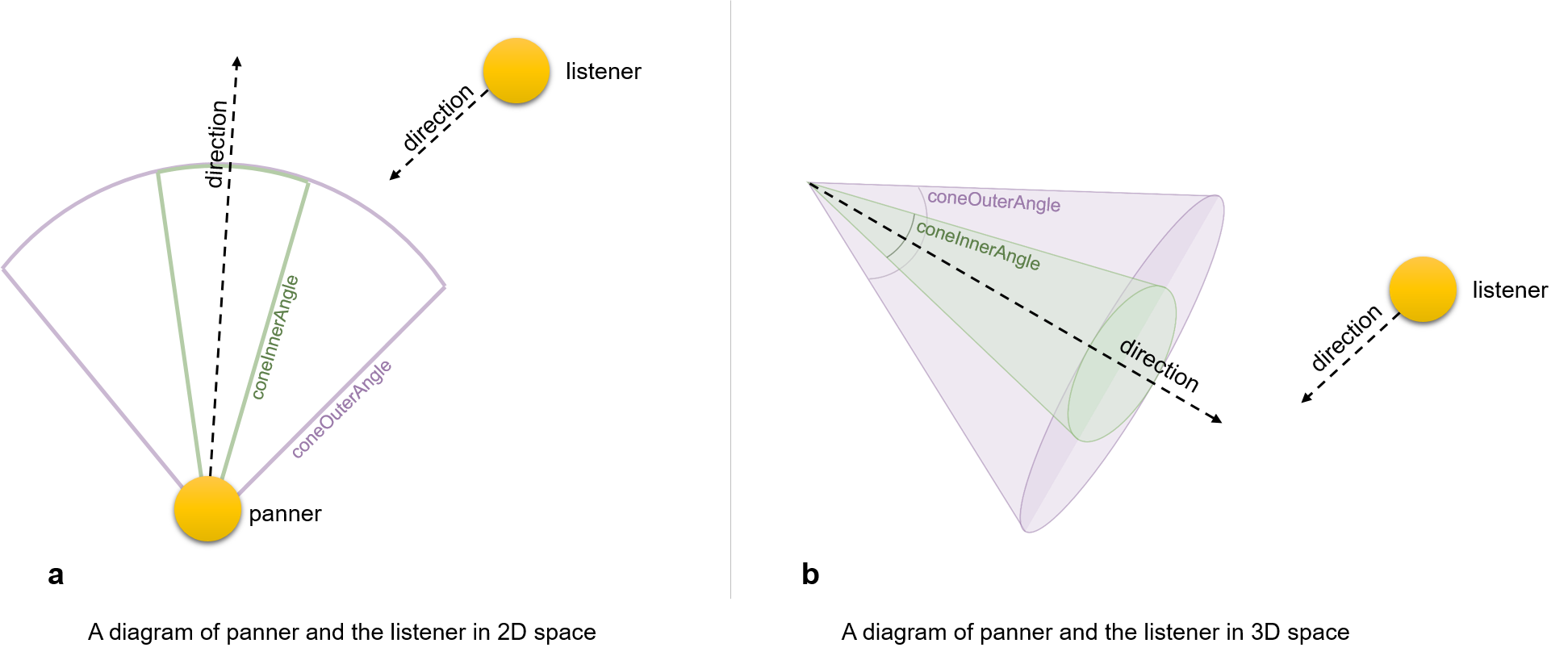
The coneInnerAngle is centered along direction and defines the inner conical volume, inside of which no source gain reduction occurs. The coneOuterAngle is centered along direction and defines an outer conical volume, within which the sound gain decreases linearly from full gain to coneOuterGain. Outside of coneOuterAngle, gain equals coneOuterGain. The value of coneOuterAngle is greater than or equal to coneInnerAngle. Corresponding gain reductions for 2D and 3D spatial panning between this source and a viewer (or ListenerPoint) are shown in Figure 16.3.
The direction. intensity, location, priority, source and spatialize fields match field definitions for Sound node.
The referenceDistance field is reference distance for reducing volume as source moves further from the listener.
The rolloffFactor field indicates how quickly volume is reduced as source moves further from listener.
The distanceModel field specifies which algorithm to use for sound attenuation, corresponding to distance between an audio source and a listener. as it moves away from the listener.
1 - rolloffFactor * (distance - referenceDistance) / (maxDistance - referenceDistance)
refDistance / (referenceDistance + rolloffFactor * (Math.max(distance, referenceDistance) - referenceDistance))
pow((Math.max(distance, referenceDistance) / referenceDistance, -rolloffFactor)
The enableHRTF field specifies whether to enable Head Related Transfer Function (HRTF) auralization, if available.
The maxDistance field is the maximum distance where sound is renderable between source and listener, after which no reduction in sound volume occurs.
Spatial sound has a conceptual role in the Web3D environments, due to highly realism scenes that can provide. Since Web Audio API is the most popular sound engine, we propose to get the necessary steps required to make X3D fully compatible with this library. In fact, we propose the enrichment of X3D with spatial sound features, using the structure and the functionality of Web Audio API.
Particularly, the Web Audio API involves handling audio operations inside an audio context and has been designed to allow modular routing. Also, the approach of Web Audio API is based on the concept of audio context, which represents the direction of audio stream flows between sound nodes.
TODO describe "cone" fields, likely need explanatory diagram.
Sound : X3DSoundNode {
  SFVec3f [in,out] direction  0 0 1 (-∞,∞)
  SFFloat [in,out] intensity  1     [0,1]
  SFVec3f [in,out] location   0 0 0 (-∞,∞)
  SFFloat [in,out] maxBack    10    [0,∞)
  SFFloat [in,out] maxFront   10    [0,∞)
  SFNode  [in,out] metadata   NULL  [X3DMetadataObject]
  SFFloat [in,out] minBack    1     [0,∞)
  SFFloat [in,out] minFront   1     [0,∞)
  SFFloat [in,out] priority   0     [0,1]
  SFNode  [in,out] source     NULL  [X3DSoundSourceNode]
  SFBool  []       spatialize TRUE
}
The Sound node specifies the spatial presentation of a sound in a X3D scene. The sound is located at a point in the local coordinate system and emits sound in an elliptical pattern (defined by two ellipsoids). The ellipsoids are oriented in a direction specified by the direction field. The shape of the ellipsoids may be modified to provide more or less directional focus from the location of the sound.
The source field specifies the sound source for the Sound node. If the source field is not specified, the Sound node will not emit audio. The source field shall specify either an AudioClip node or a MovieTexture node. If a MovieTexture node is specified as the sound source, the MovieTexture shall refer to a movie format that supports sound (EXAMPLE MPEG-1Systems, see ISO/IEC 11172-1).
The intensity field adjusts the loudness (decibels) of the sound emitted by the Sound node. The intensity field has a value that ranges from 0.0 to 1.0 and specifies a factor which shall be used to scale the normalized sample data of the sound source during playback. A Sound node with an intensity of 1.0 shall emit audio at its maximum loudness (before attenuation), and a Sound node with an intensity of 0.0 shall emit no audio. Between these values, the loudness should increase linearly from a -20 dB change approaching an intensity of 0.0 to a 0 dB change at an intensity of 1.0.
NOTE This is different from the traditional definition of intensity with respect to sound; see [SNDA].
The priority field provides a hint for the browser to choose which sounds to play when there are more active Sound nodes than can be played at once due to either limited system resources or system load. 16.2 Concepts describes a recommended algorithm for determining which sounds to play under such circumstances. The priority field ranges from 0.0 to 1.0, with 1.0 being the highest priority and 0.0 the lowest priority.
The location field determines the location of the sound emitter in the local coordinate system. A Sound node's output is audible only if it is part of the traversed scene. Sound nodes that are descended from LOD, Switch, or any grouping or prototype node that disables traversal (i.e., drawing) of its children are not audible unless they are traversed. If a Sound node is disabled by a Switch or LOD node, and later it becomes part of the traversal again, the sound shall resume where it would have been had it been playing continuously.
The Sound node has an inner ellipsoid that defines a volume of space in which the maximum level of the sound is audible. Within this ellipsoid, the normalized sample data is scaled by the intensity field and there is no attenuation. The inner ellipsoid is defined by extending the direction vector through the location. The minBack and minFront fields specify distances behind and in front of the location along the direction vector respectively. The inner ellipsoid has one of its foci at location (the second focus is implicit) and intersects the direction vector at minBack and minFront.
The Sound node has an outer ellipsoid that defines a volume of space that bounds the audibility of the sound. No sound can be heard outside of this outer ellipsoid. The outer ellipsoid is defined by extending the direction vector through the location. The maxBack and maxFront fields specify distances behind and in front of the location along the direction vector respectively. The outer ellipsoid has one of its foci at location (the second focus is implicit) and intersects the direction vector at maxBack and maxFront.
The minFront, maxFront, minBack, and maxBack fields are defined in local coordinates, and shall be greater than or equal to zero. The minBack field shall be less than or equal to maxBack, and minFront shall be less than or equal to maxFront. The ellipsoid parameters are specified in the local coordinate system but the ellipsoids' geometry is affected by ancestors' transformations.
Between the two ellipsoids, there shall be a linear attenuation ramp in loudness, from 0 dB at the minimum ellipsoid to -20 dB at the maximum ellipsoid:
attenuation = -20 × (d' / d")
where d' is the distance along the location-to-viewer vector, measured from the transformed minimum ellipsoid boundary to the viewer, and d" is the distance along the location-to-viewer vector from the transformed minimum ellipsoid boundary to the transformed maximum ellipsoid boundary (see Figure 16.2).
The spatialize field specifies if the sound is
perceived as being directionally located relative to the viewer. If
the spatialize field is TRUE
and the viewer is located between the transformed inner and outer ellipsoids,
the viewer's direction and the relative location of the Sound node should
be taken into account during playback. Details outlining the minimum
required spatialization functionality can be found in
16.2.2 Sound attenuation and spatialization.
If the spatialize field is FALSE,
directional effects are ignored, but the ellipsoid dimensions and
intensity will still affect the loudness of the sound. If the sound
source is multi-channel (EXAMPLE stereo), the source
shall
retain its channel separation during playback.
StreamAudioDestination : X3DSoundDestinationNode {
  SFString [in,out] description           ""
  MFFloat  [in,out] stream                NULL [−1,1]

  SFInt32  [in,out] channelCount          0          [0,∞)
  SFString [in,out] channelCountMode      "max"      ["max", "clamped-max", "explicit"]
  SFString [in,out] channelInterpretation "speakers" ["speakers", "discrete"]
  SFInt32  [in,out] numberOfInputs        0          [0,∞)
  SFInt32  [in,out] numberOfOutputs       0          [0,∞)
  # Mechanisms for parent-child input-output graph design remain under review
}
StreamAudioDestination is an audio destination representing a MediaStream with a single MediaStreamTrack whose kind is "audio".
TODO confirm and describe attributes
StreamAudioSource : X3DSoundSourceNode {
  SFString [in,out] description           ""
  MFFloat  [in,out] mediaStream           NULL [−1,1]

  SFInt32  [in,out] channelCount          0          [0,∞)
  SFString [in,out] channelCountMode      "max"      ["max", "clamped-max", "explicit"]
  SFString [in,out] channelInterpretation "speakers" ["speakers", "discrete"]
  SFInt32  [in,out] numberOfInputs        0          [0,∞)
  SFInt32  [in,out] numberOfOutputs       0          [0,∞)
  # Mechanisms for parent-child input-output graph design remain under review
}
StreamAudioSource operates as an audio source whose media is received from a MediaStream obtained using the WebRTC or Media Capture and Streams APIs. This media source might originate from a microphone or sound-processing channed provided by a remote peer on a WebRTC call.
TODO confirm and describe attributes
WaveShaper : X3DSoundProcessingNode {
  SFString [in,out] description           ""
  MFFloat  [in,out] curve                 []         [-1,-1]
  SFString [in,out] oversample            "none"     ["none", "2x", "4x"]

  SFInt32  [in,out] channelCount          0          [0,∞)
  SFString [in,out] channelCountMode      "max"      ["max", "clamped-max", "explicit"]
  SFString [in,out] channelInterpretation "speakers" ["speakers", "discrete"]
  SFInt32  [in,out] numberOfInputs        0          [0,∞)
  SFInt32  [in,out] numberOfOutputs       0          [0,∞)
  # Mechanisms for parent-child input-output graph design remain under review
}
WaveShaper represents a nonlinear distorter that applies a wave-shaping distortion curve to the signal. Non-linear waveshaping distortion is commonly used for both subtle non-linear warming, or more obvious distortion effects. Arbitrary non-linear shaping curves may be specified.
The curve field is an Array of floats numbers describing the distortion to apply.
The oversample field is specifies what type of oversampling (if any) should be used when applying the shaping curve. Allowed values follow. Note that for some applications, avoiding oversampling can produce a precise shaping curve.
"none": the curve is applied directly to the input samples with no oversampling."2x": oversample two times to improve the quality of the processing by avoiding some aliasing."4x": oversample four times for highest quality of the processing.The Sound component provides one level of support as specified in Table 16.2.
Table 16.2 — Sound component support levels
| Level | Prerequisites | Nodes/Features | Support |
|---|---|---|---|
|
1 |
Core 1 Time 1 |
||
| X3DSoundSourceNode (abstract) | n/a | ||
| X3DSoundNode (abstract) | n/a | ||
| AudioClip | All fields fully supported. | ||
| Sound | All fields fully supported. | ||
|
2 |
Core 1 Time 1 |
||
| All level 1 Sound nodes | All fields fully supported. | ||
| X3DSoundAnalysisNode, X3DSoundChannelNode, X3DSoundDestinationNode, X3DSoundProcessingNode | All fields fully supported. | ||
| Analyser, AudioBufferSource, AudioBufferSource, AudioDestination, BiquadFilter, ChannelMerger, ChannelSplitter, Convolver, Delay, DynamicsCompressor, ListenerPoint, MicrophoneSource, OscillatorSource, PeriodicWave, SpatialSound, StreamAudioDestination, StreamAudioSource, WaveShaper | All fields fully supported. |
![]()