Humanoid animation (H-Anim)
Humanoid animation (H-Anim)
4 Concepts
 4.1 General
This clause specifies the H-Anim core concepts, including how H-Anim figures are structured and manipulated.
Table 4.1 lists the topics for this clause.
The following conventions are used throughout this International Standard:
Italics are used for field names, and are also used when new terms are introduced and equation variables are referenced.
A fixed-space font is used for URL addresses and source code examples.
Object names are appropriately capitalized (e.g., “The Joint object is a ...”) and are represented in Bold face font.
Throughout this International Standard, references to external documents in the bibliography are denoted using the “[ABCD]” notation.
EXAMPLE [ABCD] refers to a reference described in the Bibliography.
All length measurements in this International Standard are in metres. All angle measurements are in radians.
4.2 H-Anim figuresThis International Standard specifies the structure and manipulation of H-Anim figures. H-Anim figures are articulated 3D representations that depict animated characters. While H-Anim figures are intended to represent human-like characters, they are a general concept that is not limited to the same number of limbs, heads, and other pieces body parts that are typical of human beings. A single H-Anim figure is called a humanoid.
H-Anim figures are described using the following H-Anim objects:
The Humanoid object is the root of an H-Anim figure and provides the attachment framework for all other parts of the humanoid. More detailed information about the Humanoid object is specified in 4.3 Humanoid object.
The Joint object is attached to the Humanoid object or other Joint objects using a transform the specifies the current state of articulation along with geometry associated with the attached body part. More detailed information about the Joint object is specified in 4.4 Joint object.
The Segment object specifies the attributes of the physical links between the joints of the humanoid figure. More detailed information about the Segment object is specified in 4.5 Segment object.
The Site object specifies locations at which known semantics can be associated. More detailed information about the Site object is specified in 4.6 Site object.
The Displacer object specifies information about the range of movement allowed for object in which it is embedded. More detailed information about the Displacer object is specified in 4.7 Displacer object.
The skeletal description of the H-Anim figure consists of a tree of
Joint objects that define the transformations
from the HumanoidRoot
Joint to the end effector of each appendage of the humanoid. The only requirement of
this International Standard for the definition of the skeletal
hierarchy is that it shall have a HumanoidRoot
Joint object defined. All of the other
Joint objects are optional and are not
required
for a humanoid figure to be H-Anim compliant. It is expected most
H-Anim figures will have many more joints defined than the required
HumanoidRoot. The term level of articulation (LOA), refers to the
number of articulations (or joints) that are defined for a humanoid
figure. A humanoid figure with fourteen joints is said to have a “low level of articulation”, whereas a humanoid figure with
72 joints might be said to have a “high level of
articulation”. A skeletal hierarchy
containing
only a HumanoidRoot
Joint object is the lowest level of articulation
that is allowed for an H-Anim figure.
Annex A defines four different LOAs that are common and may be used to generally categorize and describe the overall movement ability of an H-Anim human figure. However, an H-Anim human figure is constrained to conform to one of these four LOAs but may use any appropriate LOA. An individual human figure may have an alternate skeletal hierarchy suited to its purpose. This hierarchy may include any number of the optional model specific Joint objects, which may be dispersed among the standard H-Anim Joint objects. As long as the ancestral ordering of the standard Joint objects is preserved, model specific Joint objects may be inserted between the standard Joint objects in the hierarchy.
The skeletal hierarchy for H-Anim figures that are intended to represent
humans is specified in 4.9 Structure of a
humanoid.
H-Anim figures are animated by applying transformations at the joints as constrained by associated displacer information. The ability of an H-Anim figure to rearrange its limbs and body is dictated by the number of joints and segments used to specify each limb and body. More joints and segments result in a more flexible figure. Fewer joints result in a figure that is less flexible.
4.3 Humanoid objectThe geometry that specifies the body of an H-Anim humanoid figure can be described in two ways:
Each of these is described below. The interface for the Humanoid object is specified in 6.2 Humanoid.
The skeletal method specifies the geometry within the scene graph of the skeletal hierarchy, which is defined in the skeleton field of the Humanoid object. The geometry defined within the Segment objects of this hierarchy describes the body as separate geometric pieces. This method, while computationally efficient, can cause certain visual anomalies (such as seams or creases) that detract from the appearance of the humanoid figure.
The skinned method specifies the body as a continuous piece
of geometry, within the skin field
of the Humanoid object. For this method, point and normal
vector data sets are first defined in the skinCoord and skinNormal fields of the
Humanoid object
(see 6.2 Humanoid).
The data is defined in this manner to separate it from the internal
mechanisms of the Humanoid object that utilize this information. The
Humanoid object uses the coordinate and
normal vector data sets to describe the geometry that makes up the skin
surface of the humanoid figure. This surface may be implemented
as
a single indexed face set (see ISO/IEC
19775-1),
as multiple indexed face sets, or as another representation that
provides the same functionality. Depending on how the indexed
face
set is rendered within the graphics pipeline and the configuration of
the humanoid figure, it is possible that multiple indexed face sets may
provide better performance by isolating the continuous mesh changes to
localized surfaces. For this reason the specification does not
constrain the implementation of the skin surface to a single
method. The Humanoid object also manipulates the coordinate and
normal vector data sets defined in the skinCoord and skinNormal fields to reflect the
changes that occur within the skeletal scene graph of the skeleton field. In the
context
of skin deformation, each Joint object of
the
skeletal hierarchy serves the purpose of defining the coordinate frame
within which the vertices of the continuous mesh are deformed.
Additional details on this vertex manipulation can be found in the
description of how a Joint object operates.
The Joint object is used as a building block to describe the articulations of the humanoid figure. Each articulation of the humanoid figure is represented by a Joint object. These Joint objects are organized into a hierarchy that describes the inherent parent-child relationship of Joint objects of the skeleton and provides a container for information that is specific to each joint of the skeleton.
The Joint object specifies a coordinate system for itself and objects defined in its children field. This coordinate system is relative to the coordinate systems of a parent object, which in most cases is another Joint object, but which can also be the Humanoid object. Thus, the Joint object is a specialized grouping object that can only be a child of another Joint object or, in the case of the HumanoidRoot Joint, the first object of the skeletal hierarchy defined in the skeleton field of the Humanoid object.
A Joint object has two fields that allow it to manipulate individual vertices defined within the skinCoord field of the Humanoid object. Incoming rotation field events of the Joint object affect the vertices indicated by the skinCoordIndex field by a factor that is described by the corresponding values within the vertexWeight field of the Joint object. The vertexWeight field contains a list of floating point values that describe an amount of "weighting" to be used to affect the appropriate vertices (as indicated by the skinCoordIndex field) of the skinCoord field of the Humanoid object. The vertexWeight and skinCoordIndex fields are only used when a continuous mesh H-Anim model is being defined.
The Joint object is also used to store other joint-specific information. In particular, a joint name is provided so that applications can determine the identity of the Joint object. The Joint object may also contain attributes for inverse kinematics systems that control the H-Anim figure. These attributes include the upper and lower joint limits, the orientation of the joint limits, and a stiffness/resistance value. The application is responsible for enforcing these limits and there may be certain domains where an application chooses to ignore the limits.
The object interface for Joint objects is specified in
6.3 Joint.
Each body part (e.g., forearm, thigh, and/or calf) of the humanoid figure is represented by a Segment object. These Segment objects are organized in the Joint object skeletal hierarchy of the humanoid and provide a container for information that is specific to each segment of the body.
The Segment object is a specialized grouping object that provides a container for objects in its children field. A Segment object can only be defined as a child of an Joint object and shall be matched with the correct Joint object, as specified in 4.9 Structure of a humanoid.
The object interface for Segment objects is specified in 6.4 Segment.
The Site object can be used for three purposes:
Site objects that are intended to be used as attachment points from which a certain viewing perspective can be seen (such as the left and right eyes) shall be oriented so that they face in the direction the camera is looking.
A list of recommended Site objects and nominal body dimensions and levels of articulation can be found in Annex A Nominal body dimensions and levels of articulation.
Site objects are grouping objects can only be defined within the children field of a Segment object. The rotation and translation fields of the Site object define the location and orientation of the end effector within the coordinate frame of the Segment. The children field of the Site object is used to store any accessories that can be attached to the Segment object. The Site object specifies a coordinate system for objects in its children field that is relative to the coordinate systems of its parent object.
The object interface for Displacer objects is specified in 6.5 Site.
The shape of individual mesh objects may be altered according to application requirements. At the most basic level, this is done by manipulating the data stored in the coord field of the mesh objects. In the case of articulated avatars, the mesh objects reside in the Segment objects. In the case of the deformable mesh avatars, the mesh objects are specified by the skin field of the Humanoid object.
It may be necessary to identify specific groups of vertices within a mesh.
EXAMPLE The application may need to know which vertices within the skull comprise the left eyebrow.
It may also be necessary to provide “hints” as to the direction in which each vertex should move. Such information is stored in a Displacer object. For articulated avatars, the Displacer objects for a particular Segment object are stored in the displacers field of that Segment. For deformable mesh avatars, the Displacer objects are stored in the displacers fields of the Joint objects in the avatar. This information, called displacements, is specified in the local space of the particular Joint object, and transformed into the Humanoid space before being applied to the mesh.
A Displacer object can be used in three different ways. At its most basic level, it can simply be used to identify the vertices corresponding to a particular feature on the mesh. At the next level, it can be used to represent a particular muscular action which displaces the vertices in various directions. The third way in which a Displacer object can be used is to represent a complete configuration of the vertices in a mesh.
EXAMPLE In the case of a face, there might be a Displacer object for each facial expression.
Each Displacer object specifies a location, called a morph target, that can be used to modify the displacement properties of the figure. The scalar magnitude of the displacement of these Displacer objects can be dynamically driven by an external source, such as an interpolator. Thus, the mesh may be morphed smoothly using the base mesh and a linear combination of the displacements defined by the Displacer objects.
While Displacer objects are most often used to control the shape of the face, they can be used for other body parts.
EXAMPLE Displacer objects may be used to control the changing shape of an arm Segment as the arm flexes, simulating the effect of muscle inflation.
The object interface for Displacer objects is specified in 6.6 Displacer. A basic list of suggested Displacer objects is in Annex B Feature points for the human body.
This International Standard restricts the modeling of H-Anim human figures to ensure that animations designed for one H-Anim human figure are deployable to another H-Anim human figure. These restrictions specify the state of a model before any animations are applied and also ensure consistency across H-Anim human figure models.
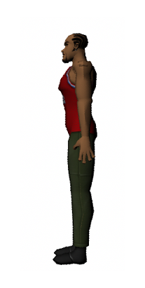
The humanoid shall be modelled in a standing position, facing in the +Z direction with +Y up and +X to the humanoid's left. The origin (0, 0, 0) shall be located at ground level, between the humanoid's feet.
The feet shall be flat on the ground, spaced apart about the same distance as the width of the hips. The bottom of the feet shall be at Y=0. The arms shall be straight and parallel to the sides of the body with the palms of the hands facing inwards towards the thighs. The hands shall be flat, with the axes of joints "1" through "3" of the fingers being parallel to the Y axis and the axis of the thumb being angled up at π/2 radians towards the +Z direction. Thus, the coordinate system for each joint in the thumb is still oriented to align with that of the overall humanoid.
Movement of the "0" joints of the fingers is typically quite limited, and the rigidity of those articulations varies from finger to finger. Further details about the placement, orientation and movement of the "0" joints can be obtained from any anatomy reference text.
The face shall be modeled with the eyebrows at rest, the mouth closed and the eyes wide open.
The humanoid shall be built with actual human size ranges in mind. All dimensions are in metres. A typical human is roughly 1.75 metres tall. Figure 4.1 depicts the default position of the humanoid:
In this position, all the joint angles shall be zero. That is, all the rotation fields in all the Joint objects shall have the default value of (0 0 1 0). In addition, the translation fields shall have the default value of (0 0 0) and the scale factors shall have the default value of (1 1 1). The only field that shall have a non-default value is centre, which is used to specify the point around which the joint (and its attached children and body segment if any) will rotate. Applying the default values for translation, rotation and scaling to all the Joints in the body shall return the body to the neutral position described above. To facilitate this, the coordinate system for each Joint object is oriented to align with that of the overall Humanoid object.
The centre field of each Joint object shall be placed so that the joints rotate in the same way that they would on a real human body.
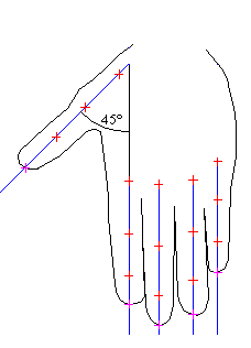
Figure 4.2 shows the orientation of the hand. The crosshairs suggest possible locations for the Joint object centre field values for the finger joints and Site object centre field values for the finger tips.
It is suggested, but not required, that all of the body Segment objects be built in place. That is, they require no translation, rotation, or scaling to be connected with their neighbors.
EXAMPLE The hand is built so that it is in the correct position relative to the forearm. The forearm is built so that it is in the correct position relative to the upper arm, and so on.
All of the coordinates of the body share a common origin, which is that of the humanoid itself. If this proves difficult for an authoring tool to implement, it is acceptable to use whatever geometric transformation mechanism is available in the encoding language to move the geometry defined within each Segment object into the correct position. Using such transformations instead of building the geometry may impact performance.
4.9 Structure of a humanoidThe human body consists of a number of segments (such as the forearm, hand and foot) that are connected to each other by joints (such as the elbow, wrist and ankle). This International Standard defines abstractions for these segments and joints that allow a human body to be described in a structured and standardized way. An H-Anim body is built as a series of nested Joint objects, each of which may have a Segment associated with it. The hierarchy in 4.9.5 Hierarchy shows the Joint:Segment object pair matching that is defined by this International Standard. If a standard H-Anim Joint object is defined, and that Joint object defines a Segment object, that Segment object shall use the appropriate name from this hierarchy.
EXAMPLE If an l_upperarm Segment object is defined, it shall be defined as a child of the l_shoulder Joint object and similiarly, if an r_knee Joint object has a Segment object defined within its children field, it shall be an r_calf Segment object.
The names of the Joint objects for the body are specified in Table 4.2.
Table 4.2 — Body Joint object names
| l_hip | l_knee | l_ankle | l_subtalar | l_midtarsal | l_metatarsal | |
| r_hip | r_knee | r_ankle | r_subtalar | r_midtarsal | r_metatarsal | |
| vl5 | vl4 | vl3 | vl2 | vl1 | ||
| vt12 | vt11 | vt10 | vt9 | vt8 | vt7 | |
| vt6 | vt5 | vt4 | vt3 | vt2 | vt1 | |
| vc7 | vc6 | vc5 | vc4 | vc3 | vc2 | vc1 |
| l_sternoclavicular | l_acromioclavicular | l_shoulder | l_elbow | l_wrist | ||
| r_sternoclavicular | r_acromioclavicular | r_shoulder | r_elbow | r_wrist | ||
| HumanoidRoot | sacroiliac (pelvis) | skullbase | ||||
The vl5 and sacroiliac Joint objects are children of the HumanoidRoot Joint object. The HumanoidRoot is stored in the humanoidBody field of the Humanoid object, but all other Joint objects are descended from either vl5 or sacroiliac. If those Joint objects are missing, lower-level Joint objects can be children of the HumanoidRoot.
The names of the Joint objects for the hands are specified in Table 4.3.
Table 4.3 — Hand Joint object names
| l_pinky0 | l_pinky1 | l_pinky2 | l_pinky3 | l_ring0 | l_ring1 | l_ring2 | l_ring3 |
| l_middle0 | l_middle1 | l_middle2 | l_middle3 | l_index0 | l_index1 | l_index2 | l_index3 |
| l_thumb1 | l_thumb2 | l_thumb3 | |||||
| r_pinky0 | r_pinky1 | r_pinky2 | r_pinky3 | r_ring0 | r_ring1 | r_ring2 | r_ring3 |
| r_middle0 | r_middle1 | r_middle2 | r_middle3 | r_index0 | r_index1 | r_index2 | r_index3 |
| r_thumb1 | r_thumb2 | r_thumb3 | |||||
Many humanoid implementations have made use of jointed facial structures to simulate facial expression. These work in a fashion similar to the facial parts of a ventriloquist’s dummy. The following is a basic set of facial Joint and Segment objects that support this type of facial animation.
The suffix “_joint” is used here because these features are controlled by muscle groups instead of actual joints, the exception being the temporomandibular Joint object. The “_joint” suffix provides a distinction between the name of the Joint object and the name of the corresponding Segment object.
All facial Joint objects are children of the skullbase Joint object. The centre of rotation of the eye and the eyelid is the geometric centre of the eyeball. The eyelid rotation defaults to zero radians, and a positive rotation of π radians shall close the eyelid until it is complete. The eyebrows are at zero radians rotation by default, and can be rotated around the middle of the eyebrow. The mouth is closed when the temporomandibular Joint object is at zero radians.
The names of the Joint objects for the face are specified in Table 4.4.
Table 4.4 — Face Joint object names
| l_eyeball_joint | r_eyeball_joint |
| l_eyebrow_joint | r_eyebrow_joint |
| l_eyelid_joint | r_eyelid_joint |
| temporomandibular |
See 4.9.6 Additional Joint and Segment objects for details on how additional facial joints may be added.
The face Joint objects from the basic set of Joint objects only provide a primitive form of facial animation. A more robust form of facial animation is specified by the MPEG-4 Facial Animation Parameters (see ISO/IEC 14496-2).
The complete hierarchy forming the basic set of Joint objects is specified in Figure 4.3 with the segment names listed beside the joints to which they are attached.
HumanoidRoot : sacrum
  sacroiliac : pelvis
  |   l_hip : l_thigh
  |     l_knee : l_calf
  |       l_ankle : l_hindfoot
  |         l_subtalar : l_midproximal
  |           l_midtarsal : l_middistal
  |             l_metatarsal : l_forefoot
  |   r_hip : r_thigh
  |     r_knee : r_calf
  |       r_ankle : r_hindfoot
  |         r_subtalar :  r_midproximal
  |           r_midtarsal : r_middistal
  |             r_metatarsal : r_forefoot
  vl5  : l5
    vl4 : l4
      vl3  : l3
        vl2 : l2
          vl1  : l1
            vt12 : t12
              vt11 : t11
                vt10  : t10
                  vt9 : t9
                    vt8 : t8
                      vt7 : t7
                        vt6  : t6
                          vt5 : t5
                            vt4 : t4
                              vt3 : t3
                                vt2 : t2
                                  vt1  : t1
                                    vc7 : c7
                                    | vc6 : c6
                                    |   vc5 : c5
                                    |     vc4  : c4
                                    |       vc3 : c3
                                    |         vc2  : c2
                                    |           vc1 : c1
                                    |             skullbase : skull
                                    |               l_eyelid_joint : l_eyelid
                                    |               r_eyelid_joint : r_eyelid
                                    |               l_eyeball_joint : l_eyeball
                                    |               r_eyeball_joint : r_eyeball
                                    |               l_eyebrow_joint : l_eyebrow
                                    |               r_eyebrow_joint : r_eyebrow
                                    |               temporomandibular : jaw
                                    l_sternoclavicular : l_clavicle
                                    | l_acromioclavicular : l_scapula
                                    |   l_shoulder : l_upperarm
                                    |     l_elbow : l_forearm
                                    |       l_wrist : l_hand
                                    |         l_thumb1 : l_thumb_metacarpal
                                    |           l_thumb2 : l_thumb_proximal
                                    |               l_thumb3 : l_thumb_distal
                                    |         l_index0 : l_index_metacarpal
                                    |           l_index1 : l_index_proximal
                                    |             l_index2 : l_index_middle
                                    |                 l_index3 : l_index_distal
                                    |         l_middle0 : l_middle_metacarpal
                                    |           l_middle1 : l_middle_proximal
                                    |             l_middle2 : l_middle_middle
                                    |               l_middle3 : l_middle_distal
                                    |         l_ring0 : l_ring_metacarpal
                                    |           l_ring1 : l_ring_proximal
                                    |             l_ring2 l_ring_middle
                                    |               l_ring3 : l_ring_distal
                                    |         l_pinky0 : l_pinky_metacarpal
                                    |           l_pinky1 : l_pinky_proximal
                                    |             l_pinky2 : l_pinky_middle
                                    |               l_pinky3 : l_pinky_distal
                                    r_sternoclavicular : r_clavicle
                                      r_acromioclavicular : r_scapula
                                        r_shoulder : r_upperarm
                                          r_elbow : r_forearm
                                            r_wrist : r_hand
                                              r_thumb1 : r_thumb_metacarpal
                                                r_thumb2 : r_thumb_proximal
                                                  r_thumb3 : r_thumb_distal
                                              r_index0 : r_index_metacarpal
                                                r_index1 : r_index_proximal
                                                  r_index2 : r_index_middle
                                                    r_index3 : r_index_distal
                                              r_middle0 : r_middle_metacarpal
                                                r_middle1 : r_middle_proximal
                                                  r_middle2 : r_middle_middle
                                                    r_middle3 : r_middle_distal
                                              r_ring0 : r_ring_metacarpal
                                                r_ring1 : r_ring_proximal
                                                  r_ring2 : r_ring_middle
                                                    r_ring3 : r_ring_distal
                                              r_pinky0 : r_pinky_metacarpal
                                                r_pinky1 : r_pinky_proximal
                                                  r_pinky2 : r_pinky_middle
                                                    r_pinky3 : r_pinky_distal
Figure 4.3 — Basic set Joint hierarchy
Additional Joint objects and body Segment objects may be defined. There are only three requirements:
No new Joint nodes are allowed within the chain of the standard Joint hierarchy. These non-standard Joint nodes may be children of either standard Joint nodes or other non-standard Joint nodes.
EXAMPLE An additional elbow cannot be added to the arm. However, new appendages (such as hair and tails) can be added to a humanoid by creating new Joint nodes that exist as children of other Joint nodes.
Additional Joint nodes shall be added in such as way as to not interfere with the movement of standard Joint nodes, even if no animation is available for them.
Animations for Joint nodes from the basic set shall not be dependent upon animations of any additional Joint nodes (or their children) that may be parented to them. Inverse kinematic systems may consider additional Joint nodes when performing calculations but are not required to do so.
Additional Joint nodes shall be given the prefix "x_" (e.g., hanim_x_pigtails) to distinguish them from basic set of Joint objects that may have similar names.