Extensible 3D (X3D)
Part 1: Architecture and base components
41 Volume rendering component
The name of this component is "VolumeRendering". This name shall be used when referring to this component in the COMPONENT statement (see 7.2.5.4 Component statement).
This component provides the ability to specify and render volumetric data sets. Table 41.1 provides links to the major topics in this clause.
Volume rendering is an alternate form of visual data representation compared to the traditional polygonal form used in the rest of this document. Whereas polygons represent a portion of an infinitely thin plane, volume data represents a three-dimensional portion of space. When polygonal data representing a volume in space is sliced, such as with a clipping plane, there is empty space. In the same situation, volumetric data shows the internals of that volume.
There are many different techniques for implementing rendering of volumetric data. This component does not define the technique used to render the data, only the type of visual output to be produced. In addition, it defines several different types of data representations for which the renderings may be applied. To implement some of the higher-complexity representations, the implementer may need to use a more complex rendering technique than the simpler representations (though this is not required). Each of the rendering nodes represents the visual output required, not the technique used to implement that visual output. Most of the rendering styles defined in this component are formally defined in [FOLEY].
Volumetric data consists of a set of aligned 2D textures. The coordinate system places the 2D textures in the volume such that each 2D texture lies in the XY-plane, with the depth increasing away from the viewer along the +Z axis.
NOTE This, effectively, inverts the 3D texture coordinates for the R axis direction, which defines them to have depth increasing along the -Z axis (see Figure 33.1).
The volume is centered around the local origin and is subject to the parent transformation hierarchy, including scales, shears and rotations.
Volumetric data represents volume information that often comes from the real world or is computationally generated.
EXAMPLE Human body scans are from the real world while simulated stress analysis of an engine part is computationally generated.
The volumetric data is typically part of a larger environment space and thus needs to be located within that space so that volumes for different parts ( e.g., an arm and leg of a single human) may be presented in a spatially correct manner. Typically, volumes are not a unit cube in size. Thus, additional dimensional information accompanies the volume to indicate its true size in the local coordinate system.
Volume rendering requires the data be provided in a volumetric form. This component uses the 3D texturing component (see 33 Texturing3D component) to represent the raw volume data, but without rendering that data directly onto polygonal surfaces. Volumetric rendering may make use of multiple 3D textures to generate a final visual form.
Data may be represented using between one and four colour components. How each colour component is to be interpreted as part of the rendering is defined for each node. Some nodes may require a specific minimum number of components or define that anything more than a specific number are to be ignored. Providing extra data may not be helpful to the implementation. In cases where not enough components are provided ( e.g., a surface normal texture only being defined with a one or two component colour image), the entire data source is ignored.
Some nodes make use of 3D textures to convey data other than colour.
EXAMPLE Normal or other vector information may be included.
For the purposes of representing 3D information, the 3D texture components shall be interpreted as defined by Table 41.2.
Table 41.2 — Mapping of texture colour components to 3D coordinates
| Color Component | 3D Coordinate |
|---|---|
| Red | X |
| Green | Y |
| Blue | Z |
| Alpha | Ignored |
If the texture provided for the field does not contain enough colour components for the data to be represented, it shall be ignored and the node's default behaviour used.
If a rendering style requires a surface normal value and is required to implicitly calculate one, the normal at a given voxel is the normalized gradient of the scalar field at that voxel location.
An implementation is free to provide whatever data reduction techniques are appropriate during pre-processing prior to rendering. Within a specific volume data representation, the implementation may also perform its own optimization techniques.
EXAMPLE Automatic mipmapping may occur.
Volume visualization data sets are not required to be represented in sizes that are powers of two. Implementations may need to internally pad the texture sizes for passing to the underlying rendering engine, but user-provided content is not required to do this.
The volume data may optionally represent segmented data sets. Doing so requires representing the data in a slightly different manner than a standard volume data set. Therefore, a separate node is provided. Segmentation data takes the form of an additional volume of data where each voxel represents a segment ID value in addition to other values represented in each voxel. The segmentation information is used by the rendering process to control how each voxel is to be rendered. It is not unusual to use segmentation information to render each segment identifier with a different style.
EXAMPLE Bone may be rendered using isosurfaces while skin may be rendered using tone shading.
This document does not explicitly handle or represent tensor data ( i.e., higher-order products of functions that are each applied to a set of variables). Nevertheless, tensor information may be rendered using the techniques in this International Standard even though no direct data is being transmitted. It is recommended that, if an application needs to know about the existence of tensor data, the metadata capabilities of this document also be used.
Volumetric data is typically given as a 3D rectangular block of information. Turning that densely packed information into something meaningful where internal structures may be discernable is the job of the rendering process. However, there is not a single uniform approach to volume rendering. A technique that is good for exposing structures for medical visualization may be poor for fluid simulation visualization.
To allow for the production of different visual outputs, the Volume rendering component separates the scenegraph into two sets of responsibilities:
In this way, the same rendering process may be used for different sets of volume data where varying rendering styles may be used to highlight different structures within the one volume.
Many rendering techniques map volume data to a visual representation through the use of another texture known as a Transfer function. This secondary texture defines the colours to use, acting as a form of lookup table. Transfer functions can be defined in one, two, or three dimensions. A one-dimensional texture capability can be achieved through the use of a 2D texture that is only one pixel wide.
Volumetric rendering requires a completely different implementation path from traditional polygonal rendering. The data represents not only surface information, but also colour and potentially lighting information as well. As such, volume rendering occupies the role in the renderable scenegraph of an X3DShapeNode rather than as individual geometry or appearance information.
Volumetric rendering is not required to follow the standard lighting equations specified in 17 Lighting component. Many techniques include the ability to self-light and self-shadow using information from the parent scene graph ( e.g., light scoping).
The volume data is rendered using one or more rendering styles. Each rendering style defines its own lighting equation that takes the colour and opacity value from the previously evaluated style, modifies the lighting equation according to the local style rules, and generates an output colour and opacity value. The first rendering style that is applied to the voxel obtains the source values directly from the voxel data using the colour and/or opacity channels as needed. Typically, the first rendering style the used to render the volume data are transfer functions and the OpacityMapVolumeStyle.
Many of these rendering styles involve non-photorealistic rendering effects. Each style presents its own lighting equation specifying how to get from the underlying voxel representation to the contributed output colour. The following are some common terms that are found in the lighting equations:
When determining the view direction for any lighting or rendering calculations, the view direction is calculated from the user's current location in the world to the current voxel being processed. Lighting and rendering style calculations are assumed to be individually calculated for each voxel.
The volumetric rendering nodes representing geometry are leaf nodes in the renderable tree. Volumetric nodes may exist as part of a shared scene graph with DEF/USE.
The minimum required voxel dimensions that shall be supported are 256x256x256.
There are no specific requirements for hardware acceleration of this component. In addition, this component does not define the specific implementation strategy to be used by a given rendering style. It is as equally valid to implement the code using simple multi-pass rendering as it is to use hardware shaders.
For minimum conformance, sensor nodes that require interaction with the geometry ( e.g., TouchSensor) shall provide intersection information based on the volume's bounds. An implementation may optionally provide real intersection information based on performing ray casting into the volume space and reporting the first non-transparent voxel hit.
Navigation and collision detection also require a minimal conformance requirement of using the bounds of the volume. In addition, the implementation may allow greater precision with non-opaque voxels in a similar manner to the sensor interactions.
X3DComposableVolumeRenderStyleNode : X3DVolumeRenderStyleNode {
  SFBool   [in,out] enabled  TRUE
  SFNode   [in,out] metadata NULL [X3DMetadataObject]
}
The X3DComposableVolumeRenderStyleNode abstract node type is the base type for all node types that allow rendering styles to be sequentially composed together to form a single renderable output. The output of one style may be used as the input of the next style. Composition in this manner is performed using the ComposedVolumeStyle node.
X3DVolumeDataNode : X3DChildNode, X3DBoundedObject {
  SFVec3f [in,out] dimensions  1 1 1    (0,∞)
  SFBool  [in out] bboxDisplay FALSE
  SFNode  [in,out] metadata    NULL     [X3DMetadataObject]
  SFBool  [in out] visible     TRUE
  SFVec3f []       bboxCenter  0 0 0    (-∞,∞)
  SFVec3f []       bboxSize    -1 -1 -1 [0,∞) or -1 -1 -1
}
The X3DVolumeDataNode abstract node type is the base type for all node types that describe volumetric data to be rendered. It sits at the same level as the polygonal X3DShapeNode (see 12.3.4 X3DShapeNode) within the scene graph structure, but defines volumetric data rather than polygonal data.
The dimensions field specifies the dimensions of this geometry in the local coordinate space using standard X3D length base units. It is assumed the volume is centered around the local origin. If the bboxSize field is set, it typically has the same value as the dimensions field.
If one of the dimension values is zero, the X3DVolumeDataNode shall be rendered as a plane. If two of the dimension values are zero, the X3DVolumeDataNode shall be rendered as a line. If all three dimension values are zero, the X3DVolumeDataNode shall be rendered as a point.
X3DVolumeRenderStyleNode : X3DNode {
  SFBool   [in,out] enabled  TRUE
  SFNode   [in,out] metadata NULL [X3DMetadataObject]
}
The X3DVolumeRenderStyleNode abstract node type is the base type for all node types that specify a specific visual rendering style to be used when rendering volume data.
The enabled field defines whether this rendering style is currently applied to the volume data. If the field is set to FALSE, the rendering shall not be applied. The result of rendering with the enabled field set to FALSE shall act as though no volume data is provided. Effectively, this allows turning on and off volume rendering of specific parts of the volume without needing to add or remove style definitions from the volume data node.
BlendedVolumeStyle : X3DComposableVolumeRenderStyleNode {
  SFBool   [in,out] enabled                 TRUE
  SFNode   [in,out] metadata                NULL       [X3DMetadataObject]
  SFNode   [in,out] renderStyle             NULL       [X3DComposableVolumeRenderStyleNode]
  SFNode   [in,out] voxels                  NULL       [X3DTexture3DNode]
  SFFloat  [in,out] weightConstant1         0.5        [0,1]
  SFFloat  [in,out] weightConstant2         0.5        [0,1]
  SFString [in,out] weightFunction1         "CONSTANT" ["CONSTANT", "ALPHA1", "ALPHA2", "TABLE",
                                                        "ONE_MINUS_ALPHA1", "ONE_MINUS_ALPHA2"]
  SFString [in,out] weightFunction2         "CONSTANT" ["CONSTANT", "ALPHA1", "ALPHA2", "TABLE",
                                                        "ONE_MINUS_ALPHA1", "ONE_MINUS_ALPHA2"]
  SFNode   [in,out] weightTransferFunction1 NULL       [X3DTexture2DNode]
  SFNode   [in,out] weightTransferFunction2 NULL       [X3DTexture2DNode]
}
The BlendedVolumeStyle combines the rendering of the parent volume data set and the rendering of a second specified volume data set into one by blending the values according to a weight function. The first data set is the data set that is specified by the parent VolumeData or SegmentedVolumeData node. The second data set and its render style is defined by the voxels and renderStyle fields specified by this BlendedVolumeStyle node. For the latter case, the value specified by the renderStyle field is applied to the voxels specified by the voxels field. The result is blended with the current state of voxels from the parent VolumeData or SegmentedVolumeData node. Those voxels are either the original parent voxels with default OpacityMapVolumeStyle applied or the result of any previous renderStyle values having been applied by a ComposedVolumeStyle node.
The final colour is determined by:
Cg = clamp[0-1](Cv × w1 + Cblend × w2)
Og = clamp[0-1](Ov × w1 + Oblend × w2)
where Cblend and Oblend is the color and alpha value of the second data set after the rendering style has been applied. The values of w1 and w2 depend on the weightFunction1 and weightFunction2 fields, respectively, as defined in Table 41.3.
Table 41.3 — Weight function types
| Value | Description of weightFunction1 | Description of weightFunction2 |
|---|---|---|
| "CONSTANT" | Use weightConstant1. | Use weightConstant2. |
| "ALPHA1" | Use Ov. | Use Ov. |
| "ALPHA2" | Use Oblend. | Use Oblend. |
| "ONE_MINUS_ALPHA1" | Use 1 - Ov. | Use 1 - Ov. |
| "ONE_MINUS_ALPHA2" | Use 1 - Oblend. | Use 1 - Oblend. |
| "TABLE" |
Use the lookup value for texture coordinate (Ov, Oblend) in weightTransferFunction1 and map to weight value according to Table 41.4 or use Ov if weightTransferFunction1 is NULL. |
Use the lookup value for texture coordinate (Ov, Oblend) in weightTransferFunction2 and map to weight value according to Table 41.4 or use Ov if weightTransferFunction2 is NULL. |
The weightTransferFunction1 and weightTransferFunction2 fields specify two-dimensional textures that are used to determine the weight values when the corresponding weight function is set to "TABLE". The output weight value depends on the number of components in the textures as specified in Table 41.4.
Table 41.4 — Transfer function to weight mapping
| Number of Texture Components | Texel Components | Weight |
|---|---|---|
| 1 | Luminance (L) | Luminance component (L) |
| 2 | Luminance Alpha (LA) | Luminance component (L) |
| 3 | RGB | Red component (R) |
| 4 | RGBA | Red component (R) |
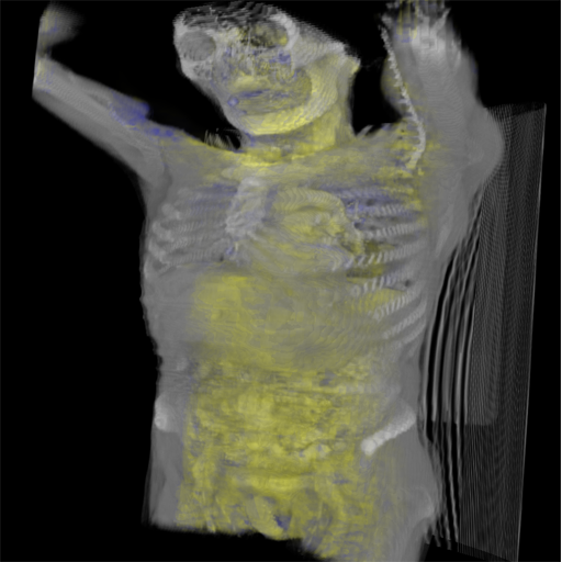
Figure 41.1 depicts a human torso and part of a skull (OpacityMapRenderStyle) blended with a blue/yellow tone-mapped volume of the internal organs. The image shows how BlendedVolumeStyle allows two different volumes to be combined, each with its own render style.
Figure 41.1 — Torso in BlendedVolumeStyle
BoundaryEnhancementVolumeStyle : X3DComposableVolumeRenderStyleNode {
  SFFloat     [in,out] boundaryOpacity  0.9     [0,1]
  SFBool      [in,out] enabled          TRUE
  SFNode      [in,out] metadata         NULL    [X3DMetadataObject]
  SFFloat     [in,out] opacityFactor    2       [0,∞)
  SFFloat     [in,out] retainedOpacity  0.2     [0,1]
  SFNode      [in,out] surfaceNormals   NULL    [X3DTexture3DNode]
}
The BoundaryEnhancementVolumeStyle node provides boundary enhancement for the volume rendering style. In this rendering style, the colour rendered is based on the gradient magnitude. Faster-changing gradients (surface normals) are darker than slower-changing gradients. Thus, regions of different density are made more visible relative to parts that are of relatively constant density. Additional information may be found in [VIS2002].
The boundaryOpacity field is the factored amount of the gradient enhancement to use.
The opacityFactor field is a power term (exponent in the equation below) that controls the slope of the opacity curve.
The retainedOpacity field specifies the normalized proportion of the initial opacity that is retained and mixed into the output.
The surfaceNormals field contains a 3D texture with at least three component values. Each voxel in the texture represents the surface normal direction for the corresponding voxel in the base data source. This texture should be identical in dimensions to the source data. If not, the implementation may interpolate or average between adjacent voxels to determine the average normal at the voxel required. If this field is empty, the implementation shall automatically determine the surface normal using algorithmic means.
The output opacity for this rendering style is obtained by combining a fraction of the volume's original opacity with the boundaryOpacity field, which is an enhancement based on the local boundary strength ( i.e., magnitude of the gradient between adjacent voxels). Colour components from the input are transferred unmodified to the output. The function used is:
Og = Ov (kgc + kgs(|Δf|)^kge)
where
Figure 41.2 shows a basic image of ventricles of the brain on the left and an image of ventricles of the brain using BoundaryEnhancementVolumeStyle on the right.
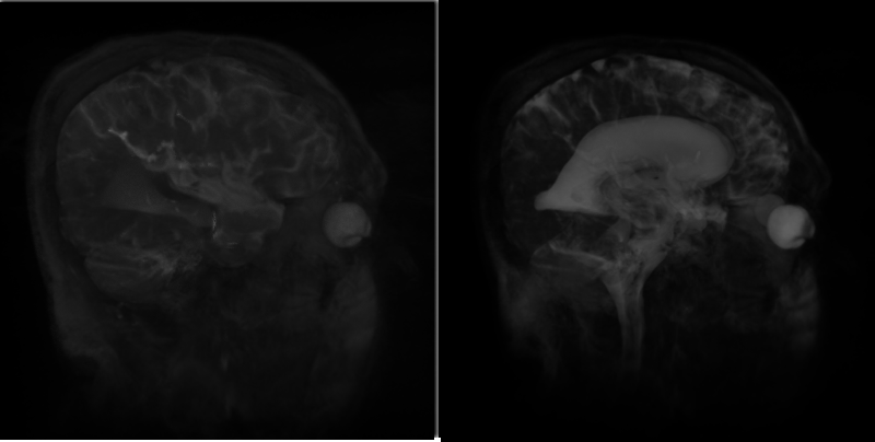
Figure 41.2 — On the left, the ventricle with default render style and default field values. On the right, the ventricle using BoundaryEnhancementVolumeStyle with default values: boundaryOpacity=0.9, opacityFactor=2, and retainedOpacity=0.2.
CartoonVolumeStyle : X3DComposableVolumeRenderStyleNode {
  SFInt32     [in,out] colorSteps       4       [1,64]
  SFBool      [in,out] enabled          TRUE
  SFNode      [in,out] metadata         NULL    [X3DMetadataObject]
  SFColorRGBA [in,out] orthogonalColor  1 1 1 1 [0,1]
  SFColorRGBA [in,out] parallelColor    0 0 0 1 [0,1]
  SFNode      [in,out] surfaceNormals   NULL    [X3DTexture3DNode]
}
The CartoonVolumeStyle generate a cartoon-style non-photorealistic rendering of the associated volumetric data. Cartoon rendering uses two colours that are rendered in a series of distinct flat-shaded sections based on the local surface normal's closeness to the average normal with no gradients in between.
The surfaceNormals field contains a 3D texture with at least three component values. Each voxel in the texture represents the surface normal direction for the corresponding voxel in the base data source. This texture should be identical in dimensions to the source data. If not, the implementation may interpolate or average between adjacent voxels to determine the average normal at the voxel required. If this field is empty, the implementation shall automatically determine the surface normal using algorithmic means.
The parallelColor field specifies the colour to be used for surface normals that are orthogonal to the viewer's current location (where the plane of the surface itself is parallel to the user's view direction).
The orthogonalColor field specifies the colour to be used for surface normals that are parallel to the viewer's current location (the plane of the surface itself is orthogonal to the user's view direction). Surfaces that are backfacing are not rendered and shall have no colour calculated for them.
The colorSteps field indicates how many distinct colours are taken from the interpolated colours and used to render the object. If the value is 1, no colour interpolation takes place and only the orthogonal colour is used to render the surface. For any other value, the colours are interpolated between parallelColor and orthogonalColor in HSV colour space for the RGB components, and linearly for the alpha component.
To determine the colours to be used, the angles for the surface normal relative to the view position are used. The range [0, π/2] is divided by colourSteps. (The two ends of the spectrum are not interpolated in this way and shall use the specified field values). For each of the interpolated ranges, other than the two ends, the midpoint angle is determined and the interpolated colour value is computed using that point.
EXAMPLE Using the default field values for CartoonVolumeStyle, the following RGBA colour are computed:
1,1,1,1 for angles [0, π/8)
0.625,0.625,0.625,1 for angles [π/8, π/4),
0.375,0.375,0.375,1 for angles [π/4, 3π/8),
0,0,0,1 for angles [3π/8, π/2]
Figure 41.3 shows a basic image of a backpack on the left and an image of the backpack using CartoonVolumeStyle on the right.
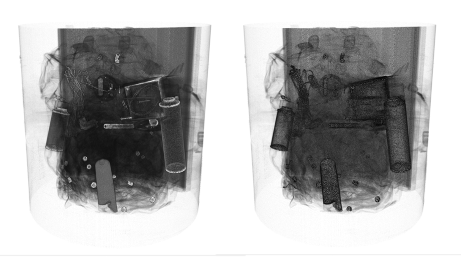
Figure 41.3 — Default volume style on left and CartoonVolumeStyle on right
ComposedVolumeStyle : X3DComposableVolumeRenderStyleNode {
  SFBool [in,out] enabled     TRUE
  SFNode [in,out] metadata    NULL  [X3DMetadataObject]
  MFNode [in,out] renderStyle []    [X3DComposableVolumeRenderStyleNode]
}
The ComposedVolumeStyle node is a rendering style node that allows compositing multiple rendering styles together into a single rendering pass.
EXAMPLE ComposedVolumeStyle is used to render a simple volume with both edge and silhouette rendering styles.
The renderStyle field contains a list of contributing rendering style nodes or node references that can be applied to the object. The implementation shall apply each rendering style strictly in the order declared starting with the first rendering style in the renderStyle field.
Figure 41.4 shows a basic image of a backpack on the left and an image of the backpack using ComposedVolumeStyle on the right that combines EdgeEnhancementVolumeStyle with SilhouetteEnhancementVolumeStyle.
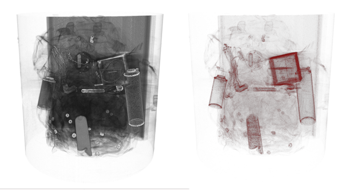
Figure 41.4 — Default volume style on left and ComposedVolumeStyle on right
EdgeEnhancementVolumeStyle : X3DComposableVolumeRenderStyleNode {
  SFColorRGBA [in,out] edgeColor         0 0 0 1 [0,1]
  SFBool      [in,out] enabled           TRUE
  SFFloat     [in,out] gradientThreshold 0.4     [0,π]
  SFNode      [in,out] metadata          NULL    [X3DMetadataObject]
  SFNode      [in,out] surfaceNormals    NULL    [X3DTexture3DNode]
}
The EdgeEnhancementVolumeStyle node specifies edge enhancement for the volume rendering style. Enhancement of the basic volume is provided by darkening voxels based on their orientation relative to the view direction. Perpendicular voxels are coloured according to the edgeColor while voxels parallel are not changed at all. A threshold can be set where the proportion of how close to parallel the direction needs to be before no colour changes are made.
The gradientThreshold field defines the minimum angle (in radians) away from the view direction vector for the surface normal before any enhancement is applied.
The edgeColor field defines the colour to be used to highlight the edges.
The surfaceNormals field contains a 3D texture with at least three component values. Each voxel in the texture represents the surface normal direction for the corresponding voxel in the base data source. This texture should be identical in dimensions to the source data. If not, the implementation may interpolate or average between adjacent voxels to determine the average normal at the voxel required. If this field is empty, the implementation shall automatically determine the surface normal using algorithmic means.
The final colour is determined by:
Cg = Cv if (| n . V|) ≥
cos(gradientThreshold);
Cv × (| n . V|) + edgeColor
× (1 - (| n . V|)) otherwise.
Og = Ov
Figure 41.5 shows a basic image of a human brain on the left and an image of the human brain using EdgeEnhancementVolumeStyle on the right.
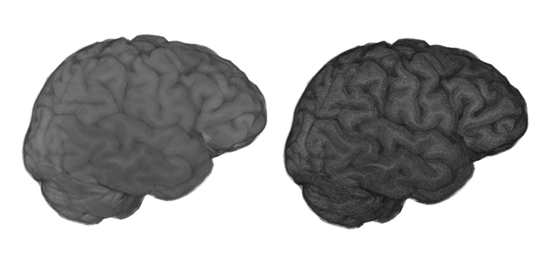
Figure 41.5 — Default volume style on left and EdgeEnhancementVolumeStyle on right
IsoSurfaceVolumeData : X3DVolumeDataNode {
  SFFloat [in,out] contourStepSize  0        (-∞,∞)
  SFVec3f [in,out] dimensions       1 1 1    (0,∞)
  SFBool  [in out] bboxDisplay      FALSE
  SFNode  [in,out] gradients        NULL     [X3DTexture3DNode]
  SFNode  [in,out] metadata         NULL     [X3DMetadataObject]
  MFNode  [in,out] renderStyle      []       [X3DVolumeRenderStyleNode]
  SFFloat [in,out] surfaceTolerance 0        [0,∞)
  MFFloat [in,out] surfaceValues    []       (-∞,∞)
  SFNode  [in,out] voxels           NULL     [X3DTexture3DNode]
  SFBool  [in out] visible          TRUE
  SFVec3f []       bboxCenter       0 0 0    (-∞,∞)
  SFVec3f []       bboxSize         -1 -1 -1 [0,∞) or -1 -1 -1
}
The IsoSurfaceVolumeData node specifies one or more surfaces extracted from a voxel data set. A surface is defined as the boundary between regions in the volume where the voxel values are larger than a given value (the iso value) on one side of the boundary and smaller on the other side and the gradient magnitude is larger than surfaceTolerance. The gradients field may be used to provide explicit per-voxel gradient direction information for determining surface boundaries rather than having it implicitly calculated by the implementation.
This data representation has one of three possible modes of operation based on the values of the two fields surfaceValues and contourStepSize.
EXAMPLE With a surface value of 0.25 and a step size of 0.1, any additional isosurfaces at 0.05, 0.15, 0.35, 0.45, ... shall also be rendered. If contourStepSize is left at the default value of zero, only that single isovalue is rendered as a surface.
NOTE The contourStepSize is allowed to be negative so that stepping proceeds in a negative direction.
For each isosurface extracted from the data set, a separate render style may be assigned using the renderStyle node. The rendering styles are taken from the renderStyles field corresponding to the index of the surface value defined. In the case where automatic contours are being extracted using the step size, the explicit surface value shall use the first declared render style. Then render styles are assigned starting from the smallest iso-value. In all cases, if there are insufficient render styles defined for the number of isosurfaces to be rendered, the last style shall be used for all surfaces that do not have an explicit style assigned.
Ov is defined to be 1 for this volume data regardless of the number of components in the provided volume data texture.
Figure 41.6 shows an IsoSurfaceVolume image of a skull using CartoonVolumeStyle.
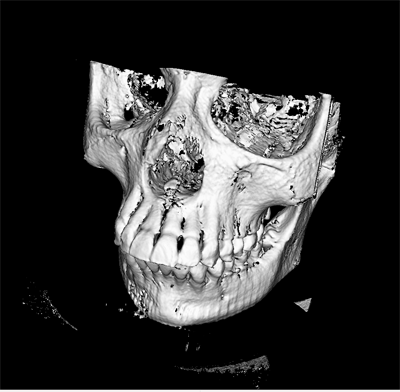
Figure 41.6 — IsoSurface volume data using CartoonVolumeStyle
OpacityMapVolumeStyle : X3DComposableVolumeRenderStyleNode {
  SFBool [in,out] enabled          TRUE
  SFNode [in,out] metadata         NULL [X3DMetadataObject]
  SFNode [in,out] transferFunction NULL [X3DTexture2DNode,X3DTexture3DNode]
}
The OpacityMapVolumeStyle specifies that the associated volumetric data is to be rendered using the opacity mapped to a transfer function texture. This is the default rendering style if no other X3DComposableVolumeRenderStyleNode is defined for the volume data.
The transferFunction field holds a single texture representation in either two or three dimensions that maps the voxel data values to a specific colour output. If no value is supplied for this field, the default implementation shall generate a 256x1 alpha-only image that blends from completely transparent at pixel 0 to fully opaque at pixel 255.The texture may be any number of dimensions and any number of components. The voxel values are used as lookup coordinates into the transfer function texture, where the texel value represents the output colour.
Components are mapped from the voxel data to the transfer function in a component-wise fashion. The first component of the voxel data is an index into the first dimension of the transferFunction texture (S). Similarly, T, R, and Q are indices into the second, third, and fourth dimensions of the transferFunction texture (see Table 41.5). If there are more components defined in the voxel data than there dimensions in the transfer function, the extra components are ignored. If there are more dimensions in the transfer function texture than the voxel data, the extra dimensions in the transfer function are ignored (effectively treating the voxel component data as a value of zero for the extra dimension). This mapping locates the texel value in the texture, which is then used as the output for this style.
Table 41.5 — Transfer function mapping from texture type to texture coordinate
| Number of Texture Components | Texture Components | Transfer Function Texture Coordinates |
|---|---|---|
| 1 | Luminance | S ← luminance (L) |
| 2 | Luminance Alpha | S, T ← luminance, alpha (LA) |
| 3 | RGB | S, T, R ← red, green, blue (RGB) |
| 4 | RGBA | S, T, R, Q ← red, green, blue, alpha (RGBA) |
The colour value is treated like a normal texture with the colour mapping as defined in Table 41.6.
Table 41.6 — Transfer function mapping from texture type to output colour
| Texture Components | Red | Green | Blue | Alpha |
|---|---|---|---|---|
| Luminance (L) | L | L | L | 1 |
| Luminance Alpha (LA) | L | L | L | A |
| RGB | R | G | B | 1 |
| RGBA | R | G | B | A |
Figure 41.7 shows a basic image of a backpack on the left and an image of the backpack using OpacityMapVolumeStyle on the right.
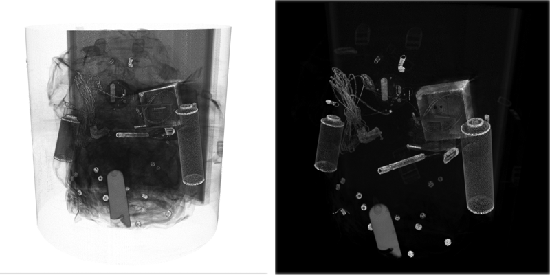
Figure 41.7 — Default volume style on left and OpacityMapVolumeStyle on right
ProjectionVolumeStyle : X3DVolumeRenderStyleNode {
  SFBool   [in,out] enabled            TRUE
  SFNode   [in,out] metadata           NULL  [X3DMetadataObject]
  SFFloat  [in,out] intensityThreshold 0     [0,1]
  SFString [in,put] type               "MAX" ["MAX", "MIN", "AVERAGE"]
}
The ProjectionVolumeStyle volume style node uses the voxel data directly to generate output colour based on the values of voxel data along the viewing rays from the eye point.
If the value of type is "MAX", The Maximum Intensity Projection (MIP) algorithm is used to generate the output colour. This rendering style also includes the option to use the extended form of Local Maximum Intensity Projection (LMIP, see [LMIP]). The output colour is determined by projecting rays into the voxel data from the viewer location and finding the maximum voxel value found along that ray. If the intensityThreshold value is non-zero, rendering will use the first maximum value encountered that exceeds the threshold rather than the maximum found along the entire ray. Figure 41.8 illustrates the difference in rendered value between LMIP and MIP.
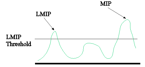
Figure 41.8 — Illustration of values selected when using MIP or LMIP volume rendering styles
If the value of type is "MIN", Minimum Intensity Projection is used. This works similar to Maximum Intensity Projection with the difference that the minimum voxel value along the ray is used.
If the value of type is "AVERAGE", Average Intensity Projection is used. In this case the average value of all voxels along the ray is used as the output colour. The intensityThreshold field is ignored. This is a simple approximation of X-Ray.
Since the output of this node is a set of intensity values, all colour components have the same value. The intensity is derived from the average of all colour components of the voxel data (though typical usage will only use single component textures). The Alpha channel is passed through as-is from the underlying data. If there is no alpha channel provided, a default alpha value of 1 is used.
Figure 41.9 shows a basic image of ventricles of the brain on the left and an image of the ventricles of the brain using MIP ProjectionVolumeStyle on the right.
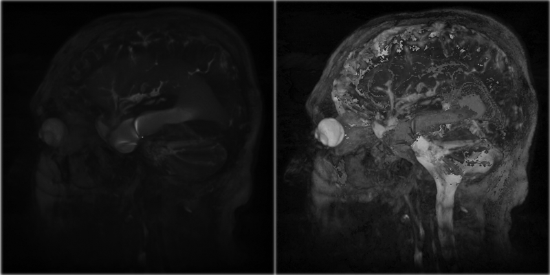
Figure 41.9 — Default volume style on left and MIP ProjectionVolumeStyle on right
SegmentedVolumeData : X3DVolumeDataNode {
  SFVec3f [in,out] dimensions         1 1 1    (0,∞)
  SFBool  [in out] bboxDisplay        FALSE
  SFNode  [in,out] metadata           NULL     [X3DMetadataObject]
  MFNode  [in,out] renderStyle        []       [X3DVolumeRenderStyleNode]
  MFBool  [in,out] segmentEnabled     []
  SFNode  [in,out] segmentIdentifiers NULL     [X3DTexture3DNode]
  SFBool  [in out] visible            TRUE
  SFNode  [in,out] voxels             NULL     [X3DTexture3DNode]
  SFVec3f []       bboxCenter         0 0 0    (-∞,∞)
  SFVec3f []       bboxSize           -1 -1 -1 [0,∞) or -1 -1 -1
}
The SegmentedVolumeData node specifies a segmented volume data set that allows for representation of different rendering styles for each segment identifier.
The renderStyle field optionally describes a particular rendering style to be used. If this field has a non-zero number of values, the defined rendering style is to be applied to the object. If the object is segmented, the index of the segment shall look up the rendering style at the given index in this array of values and apply that style to data described by that segment identifier. If the renderStyle field is not specified, the implementation shall use an OpacityMapVolumeStyle node (see 41.4.7 OpacityMapVolumeStyle) with default values.
The voxels field holds a 3D texture with the data for each voxel. For each voxel, there is a corresponding segment identifier supplied in the segmentIdentifiers field, which contains a single component texture. If the segmentIdentifiers texture is not identical in size to the main voxels, it shall be ignored. If it contains more than one colour component, only the initial component of the colour shall be used to define the segment identifier.
The segmentEnabled field specifies whether a segment is rendered or not. The indices of this array corresponds to the segment identifier. A value at index i of FALSE marks any data with the corresponding segment identifier to not be rendered. If a segment identifier is used that is greater than the length of the array, the value is assumed to be TRUE.
Figure 41.10 shows a segmented volume image of ventricles of the brain using both OpacityMapVolumeStyle for some segments ToneMappedVolumeStyle for the highlighted segments.
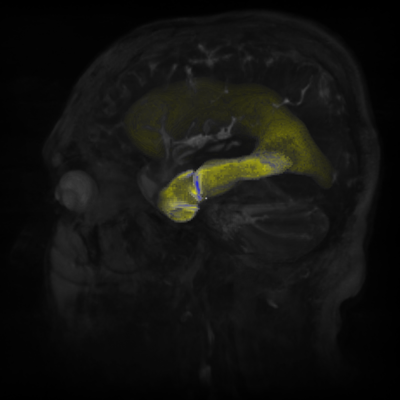
Figure 41.10 — Segmented volume data using OpacityMapVolumeStyle and ToneMappedVolumeStyle
ShadedVolumeStyle : X3DComposableVolumeRenderStyleNode {
  SFBool   [in,out] enabled        TRUE
  SFBool   [in,out] lighting       FALSE
  SFNode   [in,out] material       NULL                [X3DMaterialNode]
  SFNode   [in,out] metadata       NULL                [X3DMetadataObject]
  SFBool   [in,out] shadows        FALSE
  SFNode   [in,out] surfaceNormals NULL                [X3DTexture3DNode]
  SFString []       phaseFunction  "Henyey-Greenstein" ["Henyey-Greenstein","NONE",...]
}
The ShadedVolumeStyle node applies the Blinn-Phong illumination model ([BLINN], [PHONG]) to volume rendering. This is similar to the model used for polygonal surfaces.
Colour and opacity is determined based on whether a value has been specified for the material field. If a material field value is provided, this voxel is considered to be lit using the lighting equations below. If no material field value is provided, Oc is used as diffuse color in the same lighting equations and the specular and ambient parts are ignored.
The lighting field controls whether the rendering should calculate and apply shading effects to the visual output. If lighting is enabled the lighting equation is defined as:
Cg = IFrgb × (1 -f0)
+ f0 × (CE rgb + SUM(oni × attenuationi × spoti × ILrgb
× (ambienti + diffusei + specular i)))Og = Ov × Om
where:
attenuationi = 1 / max(a1 + a2 × dL + a3 × dL² , 1)
ambienti = Iia × CDrgb × Ca
diffusei = Ii × CDrgb × ( N · L)
specular i = Ii × CSrgb × ( N · (( L + V) / | L + V|))shininess × 128
and:
· = modified vector dot product:
if dot product < 0, then 0.0, otherwise, dot product
a1 , a2, a3 = light i attenuation
dV = distance from this voxel to viewer's position, in coordinate system of current fog node
dL = distance from light to voxel, in light's coordinate system
f0 = fog interpolant, see Table 17.5 for calculation
IFrgb = currently bound fog's color
I Lrgb = light i color
Ii = light i intensity
Iia = light i ambientIntensity
L = (PointLight/SpotLight) normalized vector from this voxel to light source i position
L = (DirectionalLight) -direction of light source i
N = normalized normal vector at this voxel (interpolated from vertex normals specified by the surfaceNormals field or automatically calculated.
Om = (1 - X3DMaterialNode transparency) if material specified, 1 otherwise
Ca = X3DMaterialNode ambientIntensity if material specified, 0 otherwise
CDrgb = diffuse colour, from a node derived from X3DMaterialNode if specified, Oc otherwise
CErgb = X3DMaterialNode emissiveColor if material specified, RGB(0,0,0) otherwise
CSrgb = X3DMaterialNode specularColor if material specified, RGB(0,0,0) otherwise
on i = 1, if light source i affects this voxel,
0, if light source i does not affect this voxel.The following conditions indicate that light source i does not affect this voxel:
- if the voxel is farther away than radius for PointLight or SpotLight;
- if the volume is outside the enclosing X3DGroupingNode and/or if the on field is FALSE;
- if the lighting field of this volume is FALSE.
shininess = X3DMaterialNode shininess if material specified, 0 otherwise
spotAngle = arccosine( -L · spotDiri)
spot BW = SpotLight i beamWidth
spot CO = SpotLight i cutOffAngle
spot i = spotlight factor, see Table 17.4 for calculation
spotDiri = normalized SpotLight i direction
SUM: sum over all light sources i
V = normalized vector from the voxel to viewer's position
If the lighting field is FALSE, the diffuse color is used without any shading effects.
Cg = CD rgb
Og = Ov × Om
The surfaceNormals field contains a 3D texture with at least three component values. Each voxel in the texture represents the surface normal direction for the corresponding voxel in the base data source. This texture should be identical in dimensions to the source data. If not, the implementation may interpolate or average between adjacent voxels to determine the average normal at the voxel required. If this field is empty, the implementation shall automatically determine the surface normal using algorithmic means.
The shadows field controls whether the rendering should calculate and apply shadows to the visual output (using global illumination model). A value of FALSE requires that no shadowing be applied. A value of TRUE requires that shadows be applied to the object. If the lighting field is set to FALSE, this field shall be ignored and no shadows generated.
The phaseFunction field is used to define the scattering model for use in an implementation using global illumination. The name defines the model type, based on standard algorithms externally defined to this document . The valid values are "NONE"(which means no scattering) and "Henyey-Greenstein" which is the Henyey-Greenstein phase function defined in [HENYEY]. Browsers may choose to support other values. If a value is specified that is not supported by the X3D browser, "Henyey-Greenstein" shall be used.
Figure 41.11 shows a basic image of a human brain on the left and an image of the human brain using ShadedVolumeStyle on the right.
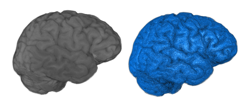
Figure 41.11 — Default volume style on left and ShadedVolumeStyle on right
SilhouetteEnhancementVolumeStyle : X3DComposableVolumeRenderStyleNode {
  SFBool  [in,out] enabled                   TRUE
  SFNode  [in,out] metadata                  NULL [X3DMetadataObject]
  SFFloat [in,out] silhouetteBoundaryOpacity 0    [0,1]
  SFFloat [in,out] silhouetteRetainedOpacity 1    [0,1]
  SFFloat [in,out] silhouetteSharpness       0.5  [0,∞)
  SFNode  [in,out] surfaceNormals            NULL [X3DTexture3DNode]
}
The SilhouetteEnhancementVolumeStyle specifies that the associated volumetric data shall be rendered with silhouette enhancement. Enhancement of the basic volume is provided by darkening voxels based on their orientation relative to the view direction. This orientation is determined by the surfaceNormals value corresponding to each voxel. Perpendicular voxels are coloured according to the edgeColor while parallel voxels are not changed at all. A threshold can be set where the proportion of how close to perpendicular the direction shall be before the values are made more opaque:
Og = Ov × (ksc + kss(1 - | n . V|) ^ kse)
where
The surfaceNormals field contains a 3D texture with at least three component values. Each voxel in the texture represents the surface normal direction for the corresponding voxel in the base data source. This texture should be identical in dimensions to the source data. If not, the implementation may interpolate or average between adjacent voxels to determine the average normal at the voxel required. If this field is empty, the implementation shall automatically determine the surface normal using algorithmic means.
Figure 41.12 shows a basic image of a skull on the left and an image of the skull using SilhouetteEnhancementVolumeStyle on the right.
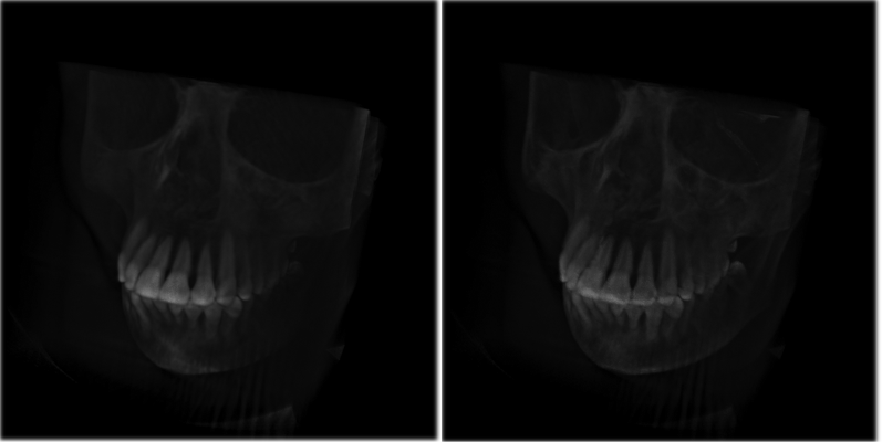
Figure 41.12 — Default volume style on left and SilhouetteEnhancementVolumeStyle on right
ToneMappedVolumeStyle : X3DComposableVolumeRenderStyleNode {
  SFColorRGBA [in,out] coolColor      0 0 1 0 [0,1]
  SFBool      [in,out] enabled        TRUE
  SFNode      [in,out] metadata       NULL    [X3DMetadataObject]
  SFNode      [in,out] surfaceNormals NULL    [X3DTexture3DNode]
  SFColorRGBA [in,out] warmColor      1 1 0 0 [0,1]
}
The ToneMappedVolumeStyle node specifies that the associated volumetric data is to be rendered using the Gooch shading model of two-toned warm/cool colouring (see [GOOCH1], [GOOCH2]). Two colours are defined, a warm colour and a cool colour. The renderer shades between them based on the orientation of the voxel relative to the user. This is not the same as the basic isosurface shading and lighting. The following colour formula is used:
cc = (1 + Li . n) × 0.5
Cg = Σ (all i) (cc × warmColor + (1 - cc) × coolColor)
where
The warmColor and coolColor fields specify the two colours to be used at the limits of the spectrum. The warmColor field is used for surfaces facing towards the light, while the coolColor is used for surfaces facing away from the light direction.
The surfaceNormals field contains a 3D texture with at least three component values. Each voxel in the texture represents the surface normal direction for the corresponding voxel in the base data source. This texture should be identical in dimensions to the source data. If not, the implementation may interpolate or average between adjacent voxels to determine the average normal at the voxel required. If this field is empty, the implementation shall automatically determine the surface normal using algorithmic means.
The final output colour is determined by combining the interpolated colour value Cg with the opacity of the corresponding voxel. Colour components of the voxel are ignored.
Figure 41.13 shows a basic image of ventricles of the brain on the left and an image of the ventricles of the brain using ToneMappedVolumeStyle on the right.
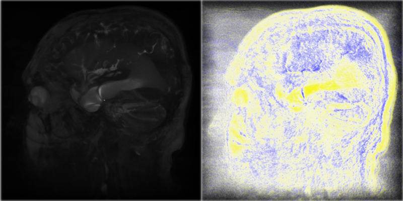
Figure 41.13 — Default volume style on left and ToneMappedVolumeStyle on right
VolumeData : X3DVolumeDataNode {
  SFVec3f [in,out] dimensions      1 1 1    (0,∞)
  SFBool  [in out] bboxDisplay     FALSE
  SFNode  [in,out] metadata        NULL     [X3DMetadataObject]
  SFNode  [in,out] renderStyle     NULL     [X3DVolumeRenderStyleNode]
  SFNode  [in,out] voxels          NULL     [X3DTexture3DNode]
  SFBool  [in out] visible         TRUE
  SFVec3f []       bboxCenter      0 0 0    (-∞,∞)
  SFVec3f []       bboxSize        -1 -1 -1 [0,∞) or -1 -1 -1
}
The VolumeData node specifies a simple non-segmented volume data set that uses a single rendering style node for the complete volume.
The renderStyle field allows the user to specify a single specific rendering technique to be used on this volumetric object. If the renderStyle field is not specified, the implementation shall use an OpacityMapVolumeStyle node (see 41.4.7 OpacityMapVolumeStyle) with default values.
The voxels field provides the raw voxel information to be used by the corresponding rendering styles. The value is any X3DTexture3DNode type and may have any number of colour components defined. The specific interpretation for the values at each voxel shall be defined by the value of the renderStyle field.
Figure 41.14 shows a basic volume image of a backpack using the default rendering style.
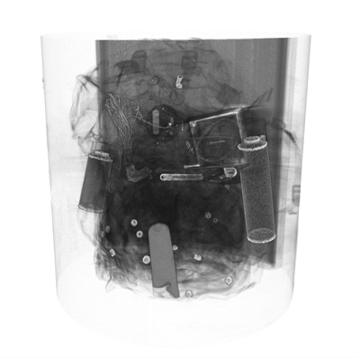
Figure 41.14 — Volume data using default volume style
The Volume Rendering component provides three levels of support as specified in Table 41.7.
Table 41.7 — Volume rendering component support levels
| Level | Prerequisites | Nodes/Features | Support |
|---|---|---|---|
| 1 | Core 1 Grouping 1 Shape 1 Rendering 1 |
||
| X3DComposableVolumeRenderStyleNode | n/a | ||
| X3DVolumeRenderStyleNode | n/a | ||
| X3DVolumeDataNode | n/a | ||
| OpacityMapVolumeStyle | Only 2D texture transfer functions need be supported. All other fields fully supported. | ||
| VolumeData | All fields fully supported. | ||
| 2 | Core 1 Grouping 1 Shape 1 Rendering 1 |
||
| All Level 1 nodes | All fields fully supported. | ||
| BoundaryEnhancementVolumeStyle | All fields fully supported. | ||
| ComposedVolumeStyle | All fields fully supported. | ||
| EdgeEnhancementVolumeStyle | All fields fully supported. | ||
| IsoSurfaceVolumeData | All fields fully supported. | ||
| OpacityMapVolumeStyle | All fields fully supported. 3D transfer functions shall be supported. | ||
| ProjectionVolumeStyle | All fields fully supported | ||
| SegmentedVolumeData | All fields fully supported. | ||
| SilhouetteEnhancementVolumeStyle | All fields fully supported. | ||
| ToneMappedVolumeStyle | All fields fully supported. | ||
| 3 | Core 1 Grouping 1 Shape 1 Rendering 1 |
||
| All Level 2 nodes | All fields fully supported. | ||
| BlendedVolumeStyle | All fields fully supported. | ||
| CartoonVolumeStyle | All fields fully supported. | ||
| ComposedVolumeStyle | All fields fully supported. | ||
| ShadedVolumeStyle | All fields fully supported except shadows. Shadows supported with at least Phong shading. | ||
| 4 | Core 1 Grouping 1 Shape 1 Rendering 1 |
||
| All Level 3 nodes | All fields fully supported. | ||
| ShadedVolumeStyle | All fields fully supported with at least Phong shading and Henyey-Greenstein phase function. Shadows fully supported. |