Extensible 3D (X3D)
Part 1: Architecture and base components
16 Sound component
The name of this component is "Sound". This name shall be used when referring to this component in the COMPONENT statement (see 7.2.5.4 Component statement).
This clause describes the Sound component of this document. This includes how sound is delivered to an X3D world as well as how sounds are accessed. Table 16.1 provides links to the major topics in this clause.
The Sound component provides a rich set of spatialized audio capabilities in a comprehensive architecture suitable for 3D models and virtual environments.
If the X3D browser does not have the resources to play all of the currently active sounds, it is recommended that the X3D browser sort the active sounds into an ordered list using the following sort keys in the order specified:
where priorityis the priority field of the Sound node, now represents the current time, startTime is the startTime field of the audio source node specified in the source field, and "intensity attenuation" refers to the intensity multiplier derived from the linear decibel attenuation ramp between inner and outer ellipsoids.
It is important that sort key 2 be used for the high priority (event and cue) sounds so that new cues are heard even when the X3D browser is "full" of currently active high priority sounds. Sort key 2 should not be used for normal priority sounds, so selection among them is based on sort key 3 (intensity at the location of the viewer).
The X3D browser shall play as many sounds from the beginning of this sorted list as it can given available resources and allowable latency between rendering. On most systems, the resources available for MIDI streams are different from those for playing sampled sounds, thus it may be beneficial to maintain a separate list to handle MIDI data.
In order to create a linear decrease in loudness as the viewer moves from the inner to the outer ellipsoid of the sound, the attenuation shall be based on a linear decibel ramp. To make the falloff consistent across X3D browsers, the decibel ramp is to vary from 0 dB at the minimum ellipsoid to -20 dB at the outer ellipsoid. Sound nodes with an outer ellipsoid that is ten times larger than the minimum will display the inverse square intensity drop-off that approximates sound attenuation in an anechoic environment.
Browsers may support spatial localization of sounds whose spatialize field is TRUE as well as their underlying sound libraries will allow. X3D browsers shall at least support stereo panning of non-MIDI sounds based on the angle between the viewer and the source. This angle is obtained by projecting the Sound location (in global space) onto the XZ plane of the viewer. Determine the angle between the Z-axis and the vector from the viewer to the transformed location, and assign a pan value in the range [0.0, 1.0] as depicted in Figure 16.1. Given this pan value, left and right channel levels can be obtained using the following equations:
leftPanFactor = 1 - pan2
rightPanFactor = 1 - (1 - pan)2
Using this technique, the loudness of the sound is modified by the intensity field value, then distance attenuation to obtain the unspatialized audio output. The values in the unspatialized audio output are then scaled by leftPanFactor and rightPanFactor to determine the final left and right output signals. The use of more sophisticated localization techniques is encouraged, but not required.
These planar gain-reduction relationships pertain to the location and relative direction of current avatar as well as any ListenerPointSource nodes.
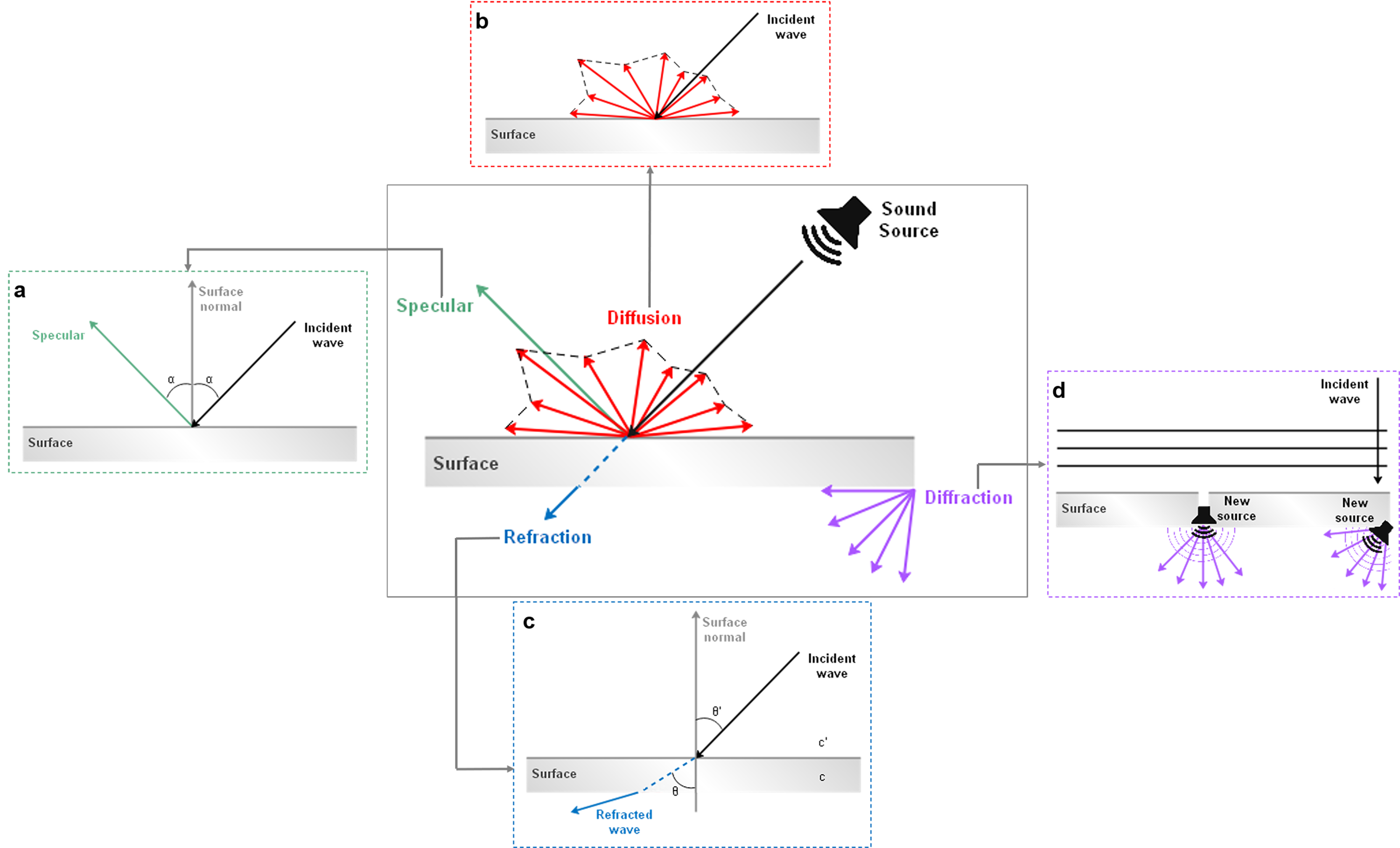
Sound-propagation techniques can be used to simulate sound waves as they travel from each source to scene listening points by taking into account the expected interactions with various objects in the scene. In other words, spatial sound rendering includes the estimation of physical effects involved in sound propagation such as surface reflection (specular, diffusion) and wave phenomena (refraction, diffraction) within a 3D scene. Figure 16.2 provides an overview of the physical models of sound propagation that are considered.
Diffraction sources are not explicitly represented in this component, and often can be handled by computational engines. Complex geometric openings may also be modeled by an audio chain including ListenerPointSource and SpatialSound to emulate sophisticated diffraction propagation paths.
If a simplified geometry alternative from Collision proxy field is available, it is used preferentially by collision-detection algorithms for sound propagation, rather than descendant children of the Collision node. Such geometric simplifications can often reduce computational costs significantly without reduction in perceived audio fidelity of 3D scene acoustics.
Sound streams can be manipulated by a variety of sound effects. Audio graphs are a powerful mechanism for modeling the diversity of real-world and electronic modifications to sound that can occur. Close integration of sound rendering and effects with 3D models and aggregate scenes provides powerful capabilities for increased realism.
Historically a wide variety of computational libraries for sound generation and propagation have been available, often with significant differences and limitations. Sound propagation and effects processing in this component are based on design patterns found in W3C Web Audio API [W3C-WebAudio]. Design goals of that specification include supporting "the capabilities found in modern game audio engines as well as some of the mixing, processing, and filtering tasks that are found in modern desktop audio production applications." These capabilities are broad, implemented in a variety of libraries, and deployed in multiple Web X3D browsers. The primary interfaces of W3C Web Audio API [W3C-WebAudio] necessary for creating audio graphs have corresponding X3D node support in this component.
Descriptions follow for a number of fields that are common to multiple nodes related to sound processing.
The channelCount field is the number of channels used when up-mixing and down-mixing connections to any inputs of a node. The default value is typically 2 except for specific nodes where its value is specially determined. This attribute has no effect for nodes with no inputs.
The channelCountMode field is used to determine the computedNumberOfChannels that controls how inputs to a node are to be mixed.
The channelInterpretation field determines how individual channels are treated when up-mixing and down-mixing connections to any inputs to the node. The default value is "speakers". This attribute has no effect for nodes with no inputs. Allowed values include the following:
The gain field is a factor that represents the amount of linear amplification to apply to the output of the node. Decibel values shall not be used. Negative gain factors negate the input signal.
X3D browsers shall support at least the wavefile format in uncompressed PCM format (see [WAV]).
It is recommended that X3D browsers support the MIDI file type 1 sound format
(see [MIDI 1.0]).
MIDI files are presumed to use the General MIDI patch set.
X3D browser support is also recommended for MIDI 2.0
(see [MIDI 2.0]
and Web MIDI API
(see [W3C-WebMIDI]).
It is also recommended that X3D browsers support the following formats:
X3DSoundChannelNode : X3DSoundNode {
  SFString [in,out] channelCountMode      "MAX"      ["MAX", "CLAMPED_MAX", "EXPLICIT"]
  SFString [in,out] channelInterpretation "SPEAKERS" ["SPEAKERS", "DISCRETE"]
  MFNode   [in,out] children              NULL       [X3DSoundChannelNode,X3DSoundProcessingNode,X3DSoundSourceNode]
  SFString [in,out] description           ""
  SFBool   [in,out] enabled               TRUE
  SFFloat  [in,out] gain                  1          (-∞,∞)
  SFNode   [in,out] metadata              NULL       [X3DMetadataObject]
  SFInt32  [out]    channelCount                     [0,∞)
}
This is the base node type for nodes that handle of channels in an audio stream, allowing them to be split or merged.
The children field is a set of input nodes, with the current node continuing creation of the audio graph.
The gain field is a factor that represents the amount of linear amplification to apply. Decibel values shall not be used. Negative gain factors negate the input signal.
The description, enabled, pauseTime, resumeTime, startTime, and stopTime inputOutput fields and the elapsedTime, isActive, and isPaused outputOnly fields, and their effects on nodes implementing this abstract node type, are discussed in detail in X3DTimeDependentNode and 8.2.4 Time-dependent nodes.
If enabled field is FALSE, the audio signal passes through unmodified and is not blocked.
X3DSoundDestinationNode : X3DSoundNode {
  SFString [in,out] description           ""
  SFBool   [in,out] enabled               TRUE
  SFFloat  [in,out] gain                  1          (-∞,∞)
  SFString [in,out] mediaDeviceID         ""
  SFNode   [in,out] metadata              NULL       [X3DMetadataObject]
  SFString [in,out] channelCountMode      "MAX"      ["MAX", "CLAMPED_MAX", "EXPLICIT"]
  SFString [in,out] channelInterpretation "SPEAKERS" ["SPEAKERS", "DISCRETE"]
  MFNode   [in,out] children              NULL       [X3DSoundChannelNode,X3DSoundProcessingNode,X3DSoundSourceNode]
  SFBool   [out]    isActive
  SFInt32  [out]    channelCount                     [0,∞)
}
This is the base node type for all sound destination nodes, which represent the final destination of an audio signal and are what the user can ultimately hear. Such nodes are often considered as audio output devices which are connected to speakers. All rendered audio that is intended to be heard gets routed to these terminal nodes.
The children field is a set of input nodes, with the current node continuing creation of the audio graph.
The gain field is a factor that represents the amount of linear amplification to apply. Decibel values shall not be used. Negative gain factors negate the input signal.
The mediaDeviceID field corresponds to the ID parameter functionality defined in W3C Web Audio API [W3C-WebAudio].
The description, enabled, pauseTime, resumeTime, startTime, and stopTime inputOutput fields and the elapsedTime, isActive, and isPaused outputOnly fields, and their effects on nodes implementing this abstract node type, are discussed in detail in X3DTimeDependentNode and 8.2.4 Time-dependent nodes.
If enabled field is FALSE, the audio signal is blocked and does not pass through.
X3DSoundNode : X3DChildNode {
  SFString [in,out] description   ""
  SFBool   [in,out] enabled       TRUE
  SFNode   [in,out] metadata      NULL [X3DMetadataObject]
}
This abstract node type is the base type for all sound nodes.
The description field specifies a textual description for the node.
The enabled field determines whether or not node functionality occurs.
X3DSoundProcessingNode : X3DTimeDependentNode {
  SFString [in,out] channelCountMode      "MAX"      ["MAX", "CLAMPED_MAX", "EXPLICIT"]
  SFString [in,out] channelInterpretation "SPEAKERS" ["SPEAKERS", "DISCRETE"]
  MFNode   [in,out] children              NULL       [X3DSoundChannelNode,X3DSoundProcessingNode,X3DSoundSourceNode]
  SFString [in,out] description           ""
  SFBool   [in,out] enabled               TRUE
  SFFloat  [in,out] gain                  1          "" (-∞,∞)
  SFNode   [in,out] metadata              NULL       [X3DMetadataObject]
  SFTime   [in,out] pauseTime             0          (-∞,∞)
  SFTime   [in,out] resumeTime            0          (-∞,∞)
  SFTime   [in,out] startTime             0          (-∞,∞)
  SFTime   [in,out] stopTime              0          (-∞,∞)
  SFTime   [in,out] tailTime              0          [0,∞)
  SFInt32  [out]    channelCount                     [0,∞)
  SFTime   [out]    elapsedTime
  SFBool   [out]    isActive
  SFBool   [out]    isPaused
}
This is the base node type for all sound processing nodes, which are used to enhance audio with filtering, delaying, changing gain, etc.
The children field is a set of input nodes, with the current node continuing creation of the audio graph.
The gain field is a factor that represents the amount of linear amplification to apply. Decibel values shall not be used. Negative gain factors negate the input signal.
The description, enabled, pauseTime, resumeTime, startTime, and stopTime inputOutput fields and the elapsedTime, isActive, and isPaused outputOnly fields, and their effects on nodes implementing this abstract node type, are discussed in detail in X3DTimeDependentNode and 8.2.4 Time-dependent nodes.
The tailTime field is duration of time that a node continues to provide output signal after the input signal becomes silent.
If enabled field is FALSE, the audio signal passes through unmodified and is not blocked.
X3DSoundSourceNode : X3DTimeDependentNode {
  SFString [in,out] description      ""
  SFBool   [in,out] enabled          TRUE
  SFFloat  [in,out] gain             1    (-∞,∞)
  SFNode   [in,out] metadata         NULL [X3DMetadataObject]
  SFTime   [in,out] pauseTime        0    (-∞,∞)
  SFTime   [in,out] resumeTime       0    (-∞,∞)
  SFTime   [in,out] startTime        0    (-∞,∞)
  SFTime   [in,out] stopTime         0    (-∞,∞)
  SFTime   [out]    elapsedTime
  SFBool   [out]    isActive
  SFBool   [out]    isPaused
}
This abstract node type is used to derive node types that can emit audio data.
The gain field is a factor that represents the amount of linear amplification to apply. Decibel values shall not be used. Negative gain factors negate the input signal.
The description, pauseTime, resumeTime, startTime, and stopTime inputOutput fields and the elapsedTime, isActive, and isPaused outputOnly fields, and their effects on nodes implementing this abstract node type, are discussed in detail in X3DTimeDependentNode and 8.2.4 Time-dependent nodes.
The isActive field may be used by other nodes to determine if the node is currently active.
Analyser :  X3DSoundProcessingNode {
  SFString [in,out] channelCountMode      "MAX"      ["MAX", "CLAMPED_MAX", "EXPLICIT"]
  SFString [in,out] channelInterpretation "SPEAKERS" ["SPEAKERS", "DISCRETE"]
  MFNode   [in,out] children              NULL       [X3DSoundChannelNode,X3DSoundProcessingNode,X3DSoundSourceNode]
  SFString [in,out] description           ""
  SFBool   [in,out] enabled               TRUE
  SFInt32  [in,out] fftSize               2048       [0,∞)
  SFInt32  [in,out] frequencyBinCount     1024       [0,∞)
  SFFloat  [in,out] gain                  1          (-∞,∞)
  SFFloat  [in,out] minDecibels           -100       (-∞,∞)
  SFFloat  [in,out] maxDecibels           -30        (-∞,∞)
  SFNode   [in,out] metadata              NULL       [X3DMetadataObject]
  SFTime   [in,out] pauseTime             0          (-∞,∞)
  SFTime   [in,out] resumeTime            0          (-∞,∞)
  SFFloat  [in,out] smoothingTimeConstant 0.8        [0,∞)
  SFTime   [in,out] startTime             0          (-∞,∞)
  SFTime   [in,out] stopTime              0          (-∞,∞)
  SFTime   [in,out] tailTime              0          [0,∞)
  SFInt32  [out]    channelCount                     [0,∞)
  SFTime   [out]    elapsedTime
  SFBool   [out]    isActive
  SFBool   [out]    isPaused
}
The Analyser node provides real-time frequency and time-domain analysis information, without any change to the input other than gain amplification.
The fftSize field is an unsigned long value representing the size of the FFT (Fast Fourier Transform) to be used to determine the frequency domain.
The frequencyBinCount field is an unsigned long value half that of the FFT size. This generally equates to the number of data values you will have to play with for the visualization.
The minDecibels field is a value representing the minimum power value in the scaling range for the FFT analysis data, for conversion to unsigned byte values.
The maxDecibels field is a value representing the maximum power value in the scaling range for the FFT analysis data, for conversion to unsigned byte values.
The smoothingTimeConstant field is a value representing the averaging constant with the last analysis frame.
The tailTime field always has a value of zero.
Fields derived from X3DSoundProcessingNode ( gain, pauseTime, resumeTime, startTime, stopTime, elapsedTime, isActive and isPaused) only affect the analysis capabilities of the node, and do not modify transfer of input signals to output.
AudioClip : X3DSoundSourceNode, X3DUrlObject {
  SFTime   [in,out] autoRefresh          0.0   [0,∞)
  SFTime   [in,out] autoRefreshTimeLimit 3600.0   [0,∞)
  SFString [in,out] description          ""
  SFBool   [in,out] enabled              TRUE
  SFFloat  [in,out] gain                 1     (-∞,∞)
  SFBool   [in,out] load                 TRUE
  SFBool   [in,out] loop                 FALSE
  SFNode   [in,out] metadata             NULL  [X3DMetadataObject]
  SFTime   [in,out] pauseTime            0     (-∞,∞)
  SFFloat  [in,out] pitch                1.0   (0,∞)
  SFTime   [in,out] resumeTime           0     (-∞,∞)
  SFTime   [in,out] startTime            0     (-∞,∞)
  SFTime   [in,out] stopTime             0     (-∞,∞)
  MFString [in,out] url                  []    [URI]
  SFTime   [out]    duration_changed
  SFTime   [out]    elapsedTime
  SFBool   [out]    isActive
  SFBool   [out]    isPaused
}
An AudioClip node specifies audio data that can be referenced by Sound nodes.
The description field specifies a textual description of the audio source. A X3D browser is not required to display the description field but may choose to do so in addition to playing the sound.
The "cycle" of an AudioClip is the length of time in seconds for one playing of the audio file at the specified pitch.
The pitch field specifies a multiplier for the rate at which sampled sound is played. Values for the pitch field shall be greater than zero. Changing the pitch field affects both the pitch and playback speed of a sound. A set_pitch event to an active AudioClip is ignored and no pitch_changed field is generated. If pitch is set to 2.0, the sound shall be played one octave higher than normal and played twice as fast. For a sampled sound, the pitch field alters the sampling rate at which the sound is played. The proper implementation of pitch control for MIDI (or other note sequence sound clips) is to multiply the tempo of the playback by the pitch value and adjust the MIDI Coarse Tune and Fine Tune controls to achieve the proper pitch change.
A duration_changed event is sent whenever there is a new value for the "normal" duration of the clip. Typically, this will only occur when the current url in use changes and the sound data has been loaded, indicating that the clip is playing a different sound source. The duration is the length of time in seconds for one cycle of the audio for a pitch set to 1.0. Changing the pitch field will not trigger a duration_changed event. A duration value of "−1" implies that the sound data has not yet loaded or the value is unavailable for some reason. A duration_changed event shall be generated if the AudioClip node is loaded when the X3D file is read or the AudioClip node is added to the scene graph.
The " cycle" of an AudioClip is the length of time in seconds for one playing of the audio at the specified pitch.
The isActive field may be used by other nodes to determine if the clip is currently active. If an AudioClip is active, it shall be playing the sound corresponding to the sound time ( i.e., in the sound's local time system with sample 0 at time 0):
t = (now − startTime) modulo (duration / pitch)
The url field specifies the URL from which the sound file is loaded. 16.2.6 Audio encoding formats describes required and recommended file format support. 9.2.1 URLs, URNs and URIs contains details on the url field.
AudioDestination : X3DSoundDestinationNode {
  SFString [in,out] channelCountMode      "MAX"      ["MAX", "CLAMPED_MAX", "EXPLICIT"]
  SFString [in,out] channelInterpretation "SPEAKERS" ["SPEAKERS", "DISCRETE"]
  MFNode   [in,out] children              NULL       [X3DSoundChannelNode,X3DSoundProcessingNode,X3DSoundSourceNode]
  SFString [in,out] description           ""
  SFBool   [in,out] enabled               TRUE
  SFFloat  [in,out] gain                  1          (-∞,∞)
  SFInt32  [in,out] maxChannelCount       2          [0,∞)
  SFString [in,out] mediaDeviceID         ""
  SFNode   [in,out] metadata              NULL       [X3DMetadataObject]
  SFBool   [out]    isActive
  SFInt32  [out]    channelCount                     [0,∞)
}
AudioDestination represents the final audio destination and is what user ultimately hears, typically from the speakers of user device. An AudioDestinationNode representing the audio hardware end-point (the normal case) can potentially output more than 2 channels of audio if the audio hardware is multi-channel.
The maxChannelCount field is the maximum number of channels that the destination is capable of supporting.
BiquadFilter : X3DSoundProcessingNode {
  SFString [in,out] channelCountMode      "MAX"      ["MAX", "CLAMPED_MAX", "EXPLICIT"]
  SFString [in,out] channelInterpretation "SPEAKERS" ["SPEAKERS", "DISCRETE"]
  MFNode   [in,out] children              NULL       [X3DSoundChannelNode,X3DSoundProcessingNode,X3DSoundSourceNode]
  SFString [in,out] description           ""
  SFFloat  [in,out] detune                0          [0,∞)
  SFBool   [in,out] enabled               TRUE
  SFFloat  [in,out] frequency             350        [0,∞)
  SFFloat  [in,out] gain                  1          (-∞,∞)
  SFNode   [in,out] metadata              NULL       [X3DMetadataObject]
  SFTime   [in,out] pauseTime             0          (-∞,∞)
  SFFloat  [in,out] qualityFactor         1          [0,∞)
  SFTime   [in,out] resumeTime            0          (-∞,∞)
  SFTime   [in,out] startTime             0          (-∞,∞)
  SFTime   [in,out] stopTime              0          (-∞,∞)
  SFTime   [in,out] tailTime              0          [0,∞)
  SFString [in,out] type                  "LOWPASS"  ["LOWPASS",   "HIGHPASS", "BANDPASS", "LOWSHELF",
                                                      "HIGHSHELF", "PEAKING",  "NOTCH",    "ALLPASS"]
  SFInt32  [out]    channelCount                     [0,∞)
  SFTime   [out]    elapsedTime
  SFBool   [out]    isActive
  SFBool   [out]    isPaused
}
BiquadFilter represents different kinds of filters, tone control devices, and graphic equalizers. Low-order filters are the building blocks of basic tone controls (bass, mid, treble), graphic equalizers, and more advanced filters. Multiple BiquadFilterNode filters can be combined to form more complex filters. The filter parameters such as frequency can be changed over time for filter sweeps, etc.
The detune field is a detune value, in cents, for the frequency.
The frequency field is the frequency at which the BiquadFilterNode will operate, in Hz.
The gain field is the amplitude gain of the filter. Its value is in dB units. The gain value is only used for lowshelf, highshelf, and peaking filters.
The qualityFactor field is Quality Factor (Q) of the filter.
The type field is the type of this BiquadFilterNode. Note that the meaning of the different properties ( frequency, detune and qualityFactor) differs depending on the type of the filter used. Descriptions for supported type values are specified in Table 16.2.
Table 16.2 — BiquadFilter type enumerations
| Enumeration | Description |
|---|---|
| "LOWPASS" |
A lowpass
filter allows frequencies below the cutoff frequency to
pass through and attenuates frequencies above the cutoff. It
implements a standard second-order resonant lowpass filter with
12dB/octave rolloff.
|
| "HIGHPASS" |
A highpass
filter is the opposite of a lowpass filter. Frequencies
above the cutoff frequency are passed through, but frequencies
below the cutoff are attenuated. It implements a standard
second-order resonant highpass filter with 12dB/octave rolloff.
|
| "BANDPASS" |
A bandpass
filter allows a range of frequencies to pass through and
attenuates the frequencies below and above this frequency
range. It implements a second-order bandpass filter.
|
| "LOWSHELF" |
The lowshelf filter allows all frequencies through, but adds a
boost (or attenuation) to the lower frequencies. It implements
a second-order lowshelf filter.
|
| "HIGHSHELF" |
The highshelf filter is the opposite of the lowshelf filter and
allows all frequencies through, but adds a boost to the higher
frequencies. It implements a second-order highshelf filter
|
| "PEAKING" |
The peaking filter allows all frequencies through, but adds a
boost (or attenuation) to a range of frequencies.
|
| "NOTCH" |
The notch filter (also known as a band-stop or
band-rejection filter) is the opposite of a bandpass
filter. It allows all frequencies through, except for a set of
frequencies.
|
| "ALLPASS" |
An allpass filter allows all frequencies through, but changes
the phase relationship between the various frequencies. It
implements a second-order allpass filter
|
BufferAudioSource : X3DSoundSourceNode, X3DUrlObject {
  SFTime   [in,out] autoRefresh           0.0        [0,∞)
  SFTime   [in,out] autoRefreshTimeLimit  3600.0     [0,∞)
  MFFloat  [in,out] buffer                []         [−1,1]
  SFTime   [in,out] bufferDuration        0          [0,∞)
  SFString [in,out] channelCountMode      "MAX"      ["MAX", "CLAMPED_MAX", "EXPLICIT"]
  SFString [in,out] channelInterpretation "SPEAKERS" ["SPEAKERS", "DISCRETE"]
  SFString [in,out] description           ""
  SFFloat  [in,out] detune                0          [0,∞)
  SFBool   [in,out] enabled               TRUE
  SFFloat  [in,out] gain                  1          (-∞,∞)
  SFBool   [in,out] load                  TRUE
  SFBool   [in,out] loop                  FALSE
  SFTime   [in,out] loopEnd               0          [0,∞)
  SFTime   [in,out] loopStart             0          [0,∞)
  SFNode   [in,out] metadata              NULL       [X3DMetadataObject]
  SFInt32  [in,out] numberOfChannels      0          [0,∞)
  SFTime   [in,out] pauseTime             0          (-∞,∞)
  SFFloat  [in,out] playbackRate          1          (-∞,∞)
  SFTime   [in,out] resumeTime            0          (-∞,∞)
  SFFloat  [in,out] sampleRate            0          [0,∞)
  SFTime   [in,out] startTime             0          (-∞,∞)
  SFTime   [in,out] stopTime              0          (-∞,∞)
  MFString [in,out] url                   []         [URI]
  SFInt32  [out]    bufferLength          0          [0,∞)
  SFInt32  [out]    channelCount                     [0,∞)
  SFTime   [out]    elapsedTime
  SFBool   [out]    isActive
  SFBool   [out]    isPaused
}
The BufferAudioSource node represents a memory-resident audio asset that can contain one or more channels. Typically the length of the Pulse-Code Modulation (PCM) data is expected to be fairly short (usually somewhat less than a minute). For longer sounds, such as music soundtracks, streaming such as StreamAudioSource should be used.
The buffer field is a data block holding the audio sample data. The buffer data format is non-interleaved 32-bit floating-point linear PCM values with a normal range of [−1,1], but values are not limited to this range.
The bufferDuration field is duration in seconds of the PCM audio buffer data, computed from the bufferLength field divided by sampleRate field.
The bufferLength field is the length of the PCM audio data in sample frames.
The detune field forms a compound field together with playbackRate that together determine a computedPlaybackRate value.
computedPlaybackRate(t) = playbackRate(t) * pow(2, detune(t) / 1200)
The loop field determines whether processing is repeated when buffer playback is complete.
The loopStart field is optional playhead position where looping begins if loop attribute is TRUE. If loopStart is greater than the duration of the buffer, looping will begin at the end of the buffer.
The loopEnd field is optional playhead position where looping ends if loop attribute is TRUE. If loopEnd value is zero, or if loopEnd is greater than the duration of the buffer, looping will end at the end of the buffer.
The numberOfChannels field is the discrete number of audio channels for this buffer.
The playbackRate field is the speed at which to render the audio stream, and is a compound parameter with detune.
The sampleRate field is the sample-rate used for the PCM audio data in samples per second.
The url field specifies the URL from which the sound file is loaded. 16.2.6 Audio encoding formats describes required and recommended file format support. 9.2.1 URLs, URNs and URIs contains details on the url field.
ChannelMerger : X3DSoundChannelNode {
  SFString [in,out] channelCountMode      "MAX"      ["MAX", "CLAMPED_MAX", "EXPLICIT"]
  SFString [in,out] channelInterpretation "SPEAKERS" ["SPEAKERS", "DISCRETE"]
  MFNode   [in,out] children              NULL       [X3DSoundChannelNode,X3DSoundProcessingNode,X3DSoundSourceNode]
  SFString [in,out] description           ""
  SFBool   [in,out] enabled               TRUE
  SFFloat  [in,out] gain                  1          (-∞,∞)
  SFNode   [in,out] metadata              NULL       [X3DMetadataObject]
  SFInt32  [out]    channelCount                     [0,∞)
}
ChannelMerger unites different input channels into a single output channel.
ChannelSelector : X3DSoundChannelNode {
  SFString [in,out] channelCountMode      "MAX"      ["MAX", "CLAMPED_MAX", "EXPLICIT"]
  SFString [in,out] channelInterpretation "SPEAKERS" ["SPEAKERS", "DISCRETE"]
  SFInt32  [in,out] channelSelection      0          [0,∞)
  MFNode   [in,out] children              NULL       [X3DSoundChannelNode,X3DSoundProcessingNode,X3DSoundSourceNode]
  SFString [in,out] description           ""
  SFBool   [in,out] enabled               TRUE
  SFFloat  [in,out] gain                  1          (-∞,∞)
  SFNode   [in,out] metadata              NULL       [X3DMetadataObject]
  SFInt32  [out]    channelCount                     [0,∞)
}
ChannelSelector selects a single channel output from all input channels. If the selected channel is not monophonic, further splitting remains feasible.
The channelSelection field indicates which channel to select, with index values beginning at 0.
ChannelSplitter : X3DSoundChannelNode {
  SFString [in,out] channelCountMode      "MAX"      ["MAX", "CLAMPED_MAX", "EXPLICIT"]
  SFString [in,out] channelInterpretation "SPEAKERS" ["SPEAKERS", "DISCRETE"]
  SFNode   [in,out] children              NULL       [X3DSoundChannelNode,X3DSoundProcessingNode,X3DSoundSourceNode]
  SFString [in,out] description           ""
  SFBool   [in,out] enabled               TRUE
  SFFloat  [in,out] gain                  1          (-∞,∞)
  SFNode   [in,out] metadata              NULL       [X3DMetadataObject]
  MFNode   [in,out] outputs               NULL       [X3DSoundChannelNode,X3DSoundProcessingNode,X3DSoundSourceNode]
  SFInt32  [out]    channelCount                     [0,∞)
}
ChannelSplitter separates the different channels of a single audio source into a set of monophonic output channels.
The outputs field is a set of output nodes receiving the split channels, and making up a section of the audio graph.
Convolver : X3DSoundProcessingNode {
  MFFloat  [in,out] buffer                []         [−1,1]
  SFString [in,out] channelCountMode      "MAX"      ["MAX", "CLAMPED_MAX", "EXPLICIT"]
  SFString [in,out] channelInterpretation "SPEAKERS" ["SPEAKERS", "DISCRETE"]
  MFNode   [in,out] children              NULL       [X3DSoundChannelNode,X3DSoundProcessingNode,X3DSoundSourceNode]
  SFString [in,out] description           ""
  SFBool   [in,out] enabled               TRUE
  SFFloat  [in,out] gain                  1          (-∞,∞)
  SFNode   [in,out] metadata              NULL       [X3DMetadataObject]
  SFBool   [in,out] normalize             FALSE
  SFTime   [in,out] pauseTime             0          (-∞,∞)
  SFTime   [in,out] resumeTime            0          (-∞,∞)
  SFTime   [in,out] startTime             0          (-∞,∞)
  SFTime   [in,out] stopTime              0          (-∞,∞)
  SFTime   [in,out] tailTime              0          [0,∞)
  SFInt32  [out]    channelCount                     [0,∞)
  SFTime   [out]    elapsedTime
  SFBool   [out]    isActive
  SFBool   [out]    isPaused
}
Convolver performs a linear convolution on a given AudioBuffer, often used to achieve a reverberation effect. Potential modifications include chorus effects, reverberation, and telephone-like speech. The idea for producing room effects is to play back a reference sound in a room, record it, and then (metaphorically) take the difference between the original sound and the recorded one. The result of this is an impulse response that captures the effect that the room has on a sound.
The buffer field represents a memory-resident audio asset (for one-shot sounds and other short audio clips). Its format is non-interleaved 32-bit linear floating-point PCM values with a normal range of [−1,1], but values are not limited to this range. It can contain one or more channels. Typically, it would be expected that the length of the PCM data would be fairly short (usually somewhat less than a minute). For longer sounds, such as music soundtracks, streaming should be used with the <audio> HTML element and AudioClip.
The normalize field is a boolean that controls whether or not the impulse response from the buffer is scaled by an equal-power normalization when the buffer field is set.
Delay : X3DSoundProcessingNode {
  SFString [in,out] channelCountMode      "MAX"      ["MAX", "CLAMPED_MAX", "EXPLICIT"]
  SFString [in,out] channelInterpretation "SPEAKERS" ["SPEAKERS", "DISCRETE"]
  MFNode   [in,out] children              NULL       [X3DSoundChannelNode,X3DSoundProcessingNode,X3DSoundSourceNode]
  SFTime   [in,out] delayTime             0          [0,∞)
  SFString [in,out] description           ""
  SFBool   [in,out] enabled               TRUE
  SFFloat  [in,out] gain                  1          (-∞,∞)
  SFTime   [in,out] maxDelayTime          1          [0,∞)
  SFNode   [in,out] metadata              NULL       [X3DMetadataObject]
  SFTime   [in,out] pauseTime             0          (-∞,∞)
  SFTime   [in,out] resumeTime            0          (-∞,∞)
  SFTime   [in,out] startTime             0          (-∞,∞)
  SFTime   [in,out] stopTime              0          (-∞,∞)
  SFInt32  [out]    channelCount                     [0,∞)
  SFTime   [out]    elapsedTime
  SFBool   [out]    isActive
  SFBool   [out]    isPaused
}
Delay causes a time delay between the arrival of input data and subsequent propagation to the output.
The delayTime field represents the amount of delay (in seconds) to apply.
The maxDelayTime field represents the maximum amount of delay (in seconds) that can be applied.
NOTE. Extremely long time delays may pose security considerations.
DynamicsCompressor : X3DSoundProcessingNode {
  SFTime   [in,out] attack         0.003      [0,∞)
  SFString [in,out] channelCountMode      "MAX"      ["MAX", "CLAMPED_MAX", "EXPLICIT"]
  SFString [in,out] channelInterpretation "SPEAKERS" ["SPEAKERS", "DISCRETE"]
  MFNode   [in,out] children              NULL       [X3DSoundChannelNode,X3DSoundProcessingNode,X3DSoundSourceNode]
  SFString [in,out] description           ""
  SFBool   [in,out] enabled               TRUE
  SFFloat  [in,out] gain                  1          (-∞,∞)
  SFFloat  [in,out] knee                  30         [0,∞)
  SFNode   [in,out] metadata              NULL       [X3DMetadataObject]
  SFTime   [in,out] pauseTime             0          (-∞,∞)
  SFFloat  [in,out] ratio                 12         [0,∞)
  SFTime   [in,out] release               0.25       [0,∞)
  SFTime   [in,out] resumeTime            0          (-∞,∞)
  SFTime   [in,out] startTime             0          (-∞,∞)
  SFTime   [in,out] stopTime              0          (-∞,∞)
  SFTime   [in,out] tailTime              0          [0,∞)
  SFFloat  [in,out] threshold             -24        [0,∞)
  SFInt32  [out]    channelCount                     [0,∞)
  SFTime   [out]    elapsedTime
  SFBool   [out]    isActive
  SFBool   [out]    isPaused
  SFFloat  [out]    reduction                        [0,∞)
}
DynamicsCompressor implements a dynamics compression effect, lowering the volume of the loudest parts of the signal and raising the volume of the softest parts.
The attack field is the amount of time (in seconds) to reduce the gain by 10dB.
The knee field contains a decibel value representing the range above the threshold where the curve smoothly transitions to the compressed portion.
The ratio field represents the amount of change, in dB, needed in the input for a 1 dB change in the output.
The reduction field represents the amount of gain reduction in dB currently applied by the compressor to the output signal. If fed no signal, then the output value is 0 (no gain reduction).
The release field represents the amount of time (in seconds) to increase the gain by 10dB.
The threshold field represents the decibel value above which the compression starts taking effect.
Gain : X3DSoundProcessingNode {
  SFString [in,out] channelCountMode      "MAX"      ["MAX", "CLAMPED_MAX", "EXPLICIT"]
  SFString [in,out] channelInterpretation "SPEAKERS" ["SPEAKERS", "DISCRETE"]
  MFNode   [in,out] children              NULL       [X3DSoundChannelNode,X3DSoundProcessingNode,X3DSoundSourceNode]
  SFString [in,out] description           ""
  SFBool   [in,out] enabled               TRUE
  SFFloat  [in,out] gain                  1          (-∞,∞)
  SFNode   [in,out] metadata              NULL       [X3DMetadataObject]
  SFTime   [in,out] pauseTime             0          (-∞,∞)
  SFTime   [in,out] resumeTime            0          (-∞,∞)
  SFTime   [in,out] startTime             0          (-∞,∞)
  SFTime   [in,out] stopTime              0          (-∞,∞)
  SFTime   [in,out] tailTime              0          [0,∞)
  SFInt32  [out]    channelCount                     [0,∞)
  SFTime   [out]    elapsedTime
  SFBool   [out]    isActive
  SFBool   [out]    isPaused
}
The Gain node amplifies or deamplifies the input signal.
The gain field is a factor that represents the amount of linear amplification to apply. Decibel values shall not be used. Negative gain factors negate the input signal.
The tailTime field always has a value of zero.
NOTE. A Gain node is similar to a Delay node with no time delay.
ListenerPointSource : X3DSoundSourceNode {
  SFString   [in,out] description        ""
  SFBool     [in,out] dopplerEnabled     FALSE
  SFBool     [in,out] enabled            TRUE
  SFInt32    [in,out] gain               1       (-∞,∞)
  SFFloat    [in,out] interauralDistance 0       [0, infinity)
  SFNode     [in,out] metadata           NULL    [X3DMetadataObject]
  SFRotation [in,out] orientation        0 0 1 0 [-1,1],(-∞,∞)
  SFVec3f    [in,out] position           0 0 0   (-∞,∞)
  SFTime     [in,out] pauseTime          0       (-∞,∞)
  SFTime     [in,out] resumeTime         0       (-∞,∞)
  SFTime     [in,out] startTime          0       (-∞,∞)
  SFTime     [in,out] stopTime           0       (-∞,∞)
  SFBool     [in,out] trackCurrentView   FALSE
  SFTime     [out]    elapsedTime
  SFBool     [out]    isActive
  SFBool     [out]    isPaused
}
ListenerPointSource represents the position and orientation of a person listening to virtual sound in the audio scene, and provides single or multiple sound channels as output. Multiple ListenerPointSource nodes can be active for sound processing.
If the dopplerEnabled field is TRUE then sound sources which are moving spatially in the transformation hierarchy, relative to the location of the ListenerPointSource node, shall be modified by applying velocity-induced frequency shifts corresponding to Doppler effect.
The interauralDistance field can be used to support binaural recording or precision sound-reproduction headgear.
If the trackCurrentView field is TRUE then position and orientation matches the user's current view.
Security consideration: an Inline scene or external prototype might include a ListenerPointSource with trackCurrentView TRUE that can eavesdrop on the virtual sound heard by the user, capturing the audio stream and then saving or streaming it surreptitiously.
MicrophoneSource : X3DSoundSourceNode {
  SFString [in,out] description    ""
  SFBool   [in,out] enabled        TRUE
  SFFloat  [in,out] gain           1    (-∞,∞)
  SFString [in,out] mediaDeviceID  ""
  SFNode   [in,out] metadata       NULL [X3DMetadataObject]
  SFTime   [in,out] pauseTime      0    (-∞,∞)
  SFTime   [in,out] resumeTime     0    (-∞,∞)
  SFTime   [in,out] startTime      0    (-∞,∞)
  SFTime   [in,out] stopTime       0    (-∞,∞)
  SFTime   [out]    elapsedTime
  SFBool   [out]    isActive
  SFBool   [out]    isPaused
}
MicrophoneSource captures input from a physical microphone in the real world.
The mediaDeviceID field is a unique identifier for the active device.
Security consideration: enabling a MicrophoneSource node has privacy and permission prerequisites.
Oscillator : X3DSoundSourceNode {
  SFString [in,out] description      ""
  SFFloat  [in,out] detune           0      [0,∞)
  SFBool   [in,out] enabled          TRUE
  SFFloat  [in,out] frequency        440.0  [0,∞)
  SFFloat  [in,out] gain             1      (-∞,∞)
  SFNode   [in,out] metadata         NULL   [X3DMetadataObject]
  SFTime   [in,out] pauseTime        0      (-∞,∞)
  SFNode   [in,out] periodicWave     NULL   [PeriodicWave]
  SFTime   [in,out] resumeTime       0      (-∞,∞)
  SFTime   [in,out] startTime        0      (-∞,∞)
  SFTime   [in,out] stopTime         0      (-∞,∞)
  SFTime   [out]    elapsedTime
  SFBool   [out]    isActive
  SFBool   [out]    isPaused
}
The OscillatorSource node represents a virtual audio source generating a periodic waveform, providing a constant tone.
The detune field is an a-rate AudioParam representing detuning of oscillation in cents (though the AudioParam returned is read-only, the value it represents is not).
The frequency field represents oscillation in hertz. The default value 440 Hz is a standard middle-A note.
The periodicWave field can hold an optional PeriodicWave node providing a regular or arbitrary periodic waveform.
PeriodicWave : X3DSoundNode {
  SFString [in,out] description ""
  SFBool   [in,out] enabled     TRUE
  SFNode   [in,out] metadata    NULL     [X3DMetadataObject]
  MFFloat  [in,out] optionsReal []
  MFFloat  [in,out] optionsImag []
  SFString [in,out] type        "SQUARE" ["SINE", "SQUARE", "SAWTOOTH", "TRIANGLE", "CUSTOM"]
}
PeriodicWave defines a periodic waveform that can be used to shape the output of an Oscillator.
The optionsReal and optionsImag fields define waveform coefficients and correspond to functionality defined in W3C Web Audio API [W3C-WebAudio].
The type field is a string which specifies the shape of waveform to play; this can be one of a number of standard values, or custom to use a PeriodicWave to describe a custom waveform. Different types of waves produce different sounds. Standard values are "SQUARE" "SINE", "SQUARE", "SAWTOOTH", "TRIANGLE", "CUSTOM". Allowed values are defined as follows:
Sound : X3DSoundNode {
  MFNode   [in,out] children   NULL  [X3DSoundChannelNode,X3DSoundProcessingNode,X3DSoundSourceNode]
  SFString [in,out] description       ""
  SFVec3f  [in,out] direction  0 0 1 (-∞,∞)
  SFBool   [in,out] enabled    TRUE
  SFFloat  [in,out] intensity  1     [0,1]
  SFVec3f  [in,out] location   0 0 0 (-∞,∞)
  SFFloat  [in,out] maxBack    10    [0,∞)
  SFFloat  [in,out] maxFront   10    [0,∞)
  SFNode   [in,out] metadata   NULL  [X3DMetadataObject]
  SFFloat  [in,out] minBack    1     [0,∞)
  SFFloat  [in,out] minFront   1     [0,∞)
  SFFloat  [in,out] priority   0     [0,1]
  SFNode   [in,out] source     NULL  [X3DSoundSourceNode]
  SFBool   []       spatialize TRUE
}
The Sound node specifies the spatial presentation of a sound in a X3D scene. The sound is located at a point in the local coordinate system and emits sound in an elliptical pattern (defined by two ellipsoids). The ellipsoids are oriented in a direction specified by the direction field. The shape of the ellipsoids may be modified to provide more or less directional focus from the location of the sound.
The source field specifies the sound source for the Sound node. If the source field is not specified, the Sound node will not emit audio. The source field shall specify either an AudioClip node or a MovieTexture node. If a MovieTexture node is specified as the sound source, the MovieTexture shall refer to a movie format that supports sound (EXAMPLE MPEG-1Systems, see ISO/IEC 11172-1).
The children field specifies additional audio-graph sound sources for this node. If multiple input signals are provided by the source and children fields, all channels are mixed together and merged prior to node operation.
The intensityfield adjusts the loudness (decibels) of the sound emitted by the Sound node. The intensity field has a value that ranges from 0.0 to 1.0 and specifies a factor which shall be used to scale the normalized sample data of the sound source during playback. A Sound node with an intensity of 1.0 shall emit audio at its maximum loudness (before attenuation), and a Sound node with an intensity of 0.0 shall emit no audio. Between these values, the loudness should increase linearly from a -20 dB change approaching an intensity of 0.0 to a 0 dB change at an intensity of 1.0.
NOTE This is different from the traditional definition of intensity with respect to sound; see [COMPMUSIC].
The priority field provides a hint for the X3D browser to choose which sounds to play when there are more active Sound nodes than can be played at once due to either limited system resources or system load. 16.2 Concepts describes a recommended algorithm for determining which sounds to play under such circumstances. The priority field ranges from 0.0 to 1.0, with 1.0 being the highest priority and 0.0 the lowest priority.
The location field determines the location of the sound emitter in the local coordinate system. A Sound node's output is audible only if it is part of the traversed scene. Sound nodes that are descended from LOD, Switch, or any grouping or prototype node that disables traversal ( i.e., drawing) of its children are not audible unless they are traversed. If a Sound node is disabled by a Switch or LOD node, and later it becomes part of the traversal again, the sound shall resume where it would have been had it been playing continuously.
The Sound node has an inner ellipsoid that defines a volume of space in which the maximum level of the sound is audible. Within this ellipsoid, the normalized sample data is scaled by the intensity field and there is no attenuation. The inner ellipsoid is defined by extending the direction vector through the location. The minBack and minFront fields specify distances behind and in front of the location along the direction vector respectively. The inner ellipsoid has one of its foci at location (the second focus is implicit) and intersects the direction vector at minBack and minFront.
The Sound node has an outer ellipsoid that defines a volume of space that bounds the audibility of the sound. No sound can be heard outside of this outer ellipsoid. The outer ellipsoid is defined by extending the direction vector through the location. The maxBack and maxFrontfields specify distances behind and in front of the location along the direction vector respectively. The outer ellipsoid has one of its foci at location (the second focus is implicit) and intersects the direction vector at maxBack and maxFront.
The minFront, maxFront, minBack, and maxBack fields are defined in local coordinates, and shall be greater than or equal to zero. The minBack field shall be less than or equal to maxBack, and minFront shall be less than or equal to maxFront. The ellipsoid parameters are specified in the local coordinate system but the ellipsoids' geometry is affected by ancestors' transformations.
Between the two ellipsoids, there shall be a linear attenuation ramp in loudness, from 0 dB at the minimum ellipsoid to -20 dB at the maximum ellipsoid:
attenuation = -20 × (d' / d")
where d' is the distance along the location-to-viewer vector, measured from the transformed minimum ellipsoid boundary to the viewer, and d" is the distance along the location-to-viewer vector from the transformed minimum ellipsoid boundary to the transformed maximum ellipsoid boundary (see Figure 16.3).
The spatialize field specifies if the sound is perceived as being directionally located relative to the viewer. If the spatializefield is TRUE and the viewer is located between the transformed inner and outer ellipsoids, the viewer's direction and the relative location of the Sound node should be taken into account during playback. Details outlining the minimum required spatialization functionality can be found in 16.2.3 Sound attenuation and spatialization. If the spatialize field is FALSE, directional effects are ignored, but the ellipsoid dimensions and intensity will still affect the loudness of the sound. If the sound source is multi-channel (EXAMPLE stereo), the source shall retain its channel separation during playback.
SpatialSound : X3DSoundNode  {
  MFNode   [in,out] children          NULL      [X3DSoundChannelNode,X3DSoundProcessingNode,X3DSoundSourceNode]
  SFFloat  [in,out] coneInnerAngle    6.2832    [0,2π]
  SFFloat  [in,out] coneOuterAngle    6.2832    [0,2π]
  SFFloat  [in,out] coneOuterGain     0         (-∞,∞)
  SFString [in,out] description       ""
  SFVec3f  [in,out] direction         0 0 1     (-∞,∞)
  SFString [in,out] distanceModel     "INVERSE" ["LINEAR" "INVERSE" "EXPONENTIAL"]
  SFBool   [in,out] dopplerEnabled    FALSE
  SFBool   [in,out] enabled           TRUE
  SFBool   [in,out] enableHRTF        FALSE
  SFFloat  [in,out] gain              1         (-∞,∞)
  SFFloat  [in,out] intensity         1         [0,1]
  SFVec3f  [in,out] location          0 0 0     (-∞,∞)
  SFFloat  [in,out] maxDistance       10000     [0,∞)
  SFNode   [in,out] metadata          NULL      [X3DMetadataObject]
  SFFloat  [in,out] priority          0         [0,1]
  SFFloat  [in,out] referenceDistance 1         [0,∞)
  SFFloat  [in,out] rolloffFactor     1         [0,∞)
  SFBool   []       spatialize        TRUE
}
SpatialSound represents a processing node which positions, emits and spatializes an audio stream in three-dimensional (3D) space. This node provides full spatialization of panner capabilities defined by W3C Web Audio API [W3C-WebAudio] within an X3D scene.
The coneInnerAngle is centered along direction and defines the inner conical volume, inside of which no source gain reduction occurs. The coneOuterAngle is centered along direction and defines an outer conical volume, within which the sound gain decreases linearly from full gain to coneOuterGain. Outside of coneOuterAngle, gain equals coneOuterGain. The value of coneOuterAngle is greater than or equal to coneInnerAngle. Corresponding gain reductions for 2D and 3D spatial panning between this source and a viewer (or ListenerPointSource) are shown in Figure 16.4.
If the dopplerEnabled field is TRUE then sound sources which are moving spatially in the transformation hierarchy, relative to the location of the ListenerPointSource node, shall be modified by applying velocity-induced frequency shifts corresponding to Doppler effect.
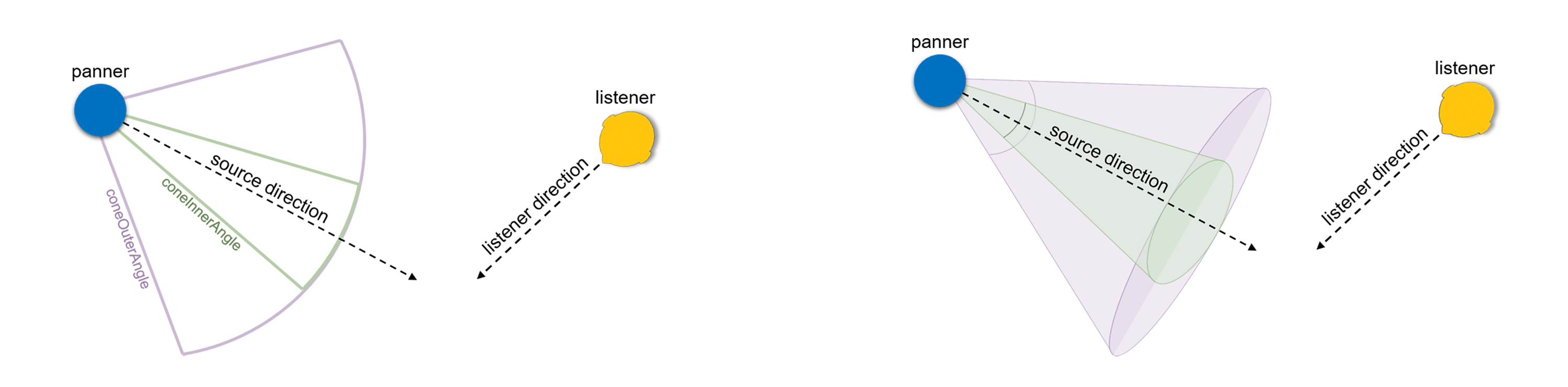
Figure 16.4 — SpatialSound Panning Gain Relationships for viewer (or ListenerPointSource)
The direction, intensity, location, priority, source and spatialize fields match field definitions for Sound node.
The referenceDistance field is reference distance for reducing volume as source moves further from the listener. For distances less than this value, volume is not reduced.
The rolloffFactor field indicates how quickly volume is reduced as source moves further from listener.
The distanceModel field specifies which algorithm to use for sound attenuation, corresponding to distance between an audio source and a listener, as it moves away from the listener.
The enableHRTF field specifies whether to enable Head Related Transfer Function (HRTF) auralization, if available.
The maxDistance field is the maximum distance where sound is renderable between source and listener, after which no reduction in sound volume occurs.
The children field specifies audio-graph sound sources for this node. If multiple input signals are provided by the children field, all channels are mixed together and merged prior to node operation.
StreamAudioDestination : X3DSoundDestinationNode {
  SFString [in,out] channelCountMode      "MAX"      ["MAX", "CLAMPED_MAX", "EXPLICIT"]
  SFString [in,out] channelInterpretation "SPEAKERS" ["SPEAKERS", "DISCRETE"]
  MFNode   [in,out] children              NULL       [X3DSoundChannelNode,X3DSoundProcessingNode,X3DSoundSourceNode]
  SFString [in,out] description           ""
  SFBool   [in,out] enabled               TRUE
  SFFloat  [in,out] gain                  1          (-∞,∞)
  SFString [in,out] mediaDeviceID         ""
  SFNode   [in,out] metadata              NULL       [X3DMetadataObject]
  MFString [in,out] streamIdentifier      []
  SFInt32  [out]    channelCount                     [0,∞)
}
StreamAudioDestination is an audio destination representing a MediaStream with a single MediaStreamTrack whose kind is "audio".
The streamIdentifier field conforms to requirements of W3C Media Capture and Streams [W3C-Media].
StreamAudioSource : X3DSoundSourceNode {
  SFString [in,out] channelCountMode      "MAX"      ["MAX", "CLAMPED_MAX", "EXPLICIT"]
  SFString [in,out] channelInterpretation "SPEAKERS" ["SPEAKERS", "DISCRETE"]
  SFString [in,out] description           ""
  SFBool   [in,out] enabled               TRUE
  SFFloat  [in,out] gain                  1          (-∞,∞)
  SFNode   [in,out] metadata              NULL       [X3DMetadataObject]
  SFTime   [in,out] pauseTime             0          (-∞,∞)
  SFTime   [in,out] resumeTime            0          (-∞,∞)
  SFTime   [in,out] startTime             0          (-∞,∞)
  SFTime   [in,out] stopTime              0          (-∞,∞)
  MFString [in,out] streamIdentifier      []
  SFInt32  [out]    channelCount                     [0,∞)
  SFTime   [out]    elapsedTime
  SFBool   [out]    isActive
  SFBool   [out]    isPaused
}
StreamAudioSource operates as an audio source whose media is received from a MediaStream obtained using the WebRTC or Media Capture and Streams APIs. This media source might originate from a remote microphone or sound-processing channel provided by a remote peer on a WebRTC call.
The streamIdentifier field conforms to requirements of W3C Media Capture and Streams [W3C-Media].WaveShaper : X3DSoundProcessingNode {
SFString [in,out] channelCountMode "MAX" ["MAX", "CLAMPED_MAX", "EXPLICIT"]
SFString [in,out] channelInterpretation "SPEAKERS" ["SPEAKERS", "DISCRETE"]
MFNode [in,out] children NULL [X3DSoundChannelNode,X3DSoundProcessingNode,X3DSoundSourceNode]
MFFloat [in,out] curve [] [-1,-1]
SFString [in,out] description ""
SFBool [in,out] enabled TRUE
SFFloat [in,out] gain 1 (-∞,∞)
SFNode [in,out] metadata NULL [X3DMetadataObject]
SFString [in,out] oversample "NONE" ["NONE", "2X", "4X"]
SFTime [in,out] pauseTime 0 (-∞,∞)
SFTime [in,out] resumeTime 0 (-∞,∞)
SFTime [in,out] startTime 0 (-∞,∞)
SFTime [in,out] stopTime 0 (-∞,∞)
SFTime [in,out] tailTime 0 [0,∞)
SFInt32 [out] channelCount [0,∞)
SFTime [out] elapsedTime
SFBool [out] isActive
SFBool [out] isPaused
}
WaveShaper represents a nonlinear distorter that applies a wave-shaping distortion curve to the signal. Non-linear waveshaping distortion is commonly used for both subtle non-linear warming, or more obvious distortion effects. Arbitrary non-linear shaping curves may be specified.
The curve field is an array of floating-point numbers describing the distortion to apply.
The oversample field is specifies what type of oversampling (if any) should be used when applying the shaping curve. Allowed values follow. Note that for some applications, avoiding oversampling can produce a precise shaping curve.
The Sound component provides one level of support as specified in Table 16.3.
Table 16.3 — Sound component support levels
| Level | Prerequisites | Nodes/Features | Support |
|---|---|---|---|
| 1 | Core 1 Time 1 |
||
| X3DSoundChannelNode (abstract) | n/a | ||
| X3DSoundDestinationNode (abstract) | n/a | ||
| X3DSoundNode (abstract) | n/a | ||
| X3DSoundProcessingNode (abstract) | n/a | ||
| X3DSoundSourceNode (abstract) | n/a | ||
| AudioClip | All fields fully supported. | ||
| Sound | All fields fully supported, children field support is optional. | ||
| 2 | Core 1 Time 1 |
||
| All level 1 Sound nodes | All fields fully supported. | ||
| Analyser | All fields fully supported. | ||
| AudioDestination | All fields fully supported. | ||
| BiquadFilter | All fields fully supported. | ||
| BufferAudioSource | All fields fully supported. | ||
| ChannelMerger | All fields fully supported. | ||
| ChannelSelector | All fields fully supported. | ||
| ChannelSplitter | All fields fully supported. | ||
| Convolver | All fields fully supported. | ||
| Delay | All fields fully supported. | ||
| DynamicsCompressor | All fields fully supported. | ||
| Gain | All fields fully supported. | ||
| ListenerPointSource | All fields fully supported. Doppler effects due to relative velocity between ListenerPointSource and sound sources are optional. | ||
| MicrophoneSource | All fields fully supported. | ||
| OscillatorSource | All fields fully supported. | ||
| PeriodicWave | All fields fully supported. | ||
| Sound | All fields fully supported. | ||
| SpatialSound | All fields fully supported. Doppler effects due to relative velocity between SpatialSound and sound sources are optional. | ||
| StreamAudioDestination | All fields fully supported. | ||
| StreamAudioSource | All fields fully supported. | ||
| WaveShaper | All fields fully supported. | ||
| 3 | Core 1 Time 1 |
||
| ListenerPointSource | All fields and capabilities fully supported. | ||
| SpatialSound | All fields and capabilities fully supported. |
![]()