Extensible 3D (X3D)
Part 1: Architecture and base components
13 Geometry3D component
 13.1 Introduction
The name of this component is "Geometry3D". This name shall be used when referring to this component in the COMPONENT statement (see 7.2.5.4 Component statement).
This clause describes the Geometry3D component of this part of ISO/IEC 19775. This includes how 3D geometry is specified and what shapes are available. Table 13.1 provides links to the major topics in this clause.
13.2 ConceptsThe geometry component consists of four types of nodes: shape, geometry, geometry property, and appearance. Together, these node types are used to describe the visual elements of a X3D world.
The Shape node associates a geometry node with nodes that define that geometry's appearance. Shape nodes must be part of the transformation hierarchy to have any visible result, and the transformation hierarchy must contain Shape nodes for any geometry to be visible (the only nodes that render visible results are Shape nodes and the background nodes in 24 Environmental effects). A Shape node contains exactly one geometry node in its geometry field, which is of type X3DGeometryNode. For more on the Shape node, see 12 Shape component.
Other components may define additional geometry node types.
Several geometry nodes contain geometric property nodes such as Coordinate, Color, ColorRGBA, and/or Normal. These nodes are specified in 11 Rendering component. The X3DTextureCoordinate nodes specified in 18 Texturing component are also geometry property nodes.
Shape nodes may specify an Appearance node that describes the appearance properties (material and texture) to be applied to the Shape's geometry. Appearance is described in 12 Shape component.
Several 3D geometry nodes share common fields to describe attributes. These fields specify the vertex ordering, if the shape is solid, if the shape contains convex faces, and at what angle a crease appears between faces, and are named ccw, solid, convex and creaseAngle, respectively. Common 3D geometry fields are described in 11 Rendering component.
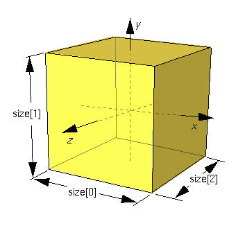
13.3 Node referenceBox : X3DGeometryNode {
SFNode [in,out] metadata NULL [X3DMetadataObject]
SFVec3f [] size 2 2 2 (0,∞)
SFBool [] solid TRUE
}
The Box node specifies a rectangular parallelepiped box centred at (0, 0, 0) in the local coordinate system and aligned with the local coordinate axes. By default, the box measures 2 units in each dimension, from -1 to +1. The size field specifies the extents of the box along the X-, Y-, and Z-axes respectively and each component value shall be greater than zero. Figure 13.1 illustrates the Box node.
Textures are applied individually to each face of the box. On the front (+Z), back (-Z), right (+X), and left (-X) faces of the box, when viewed from the outside with the +Y-axis up, the texture is mapped onto each face with the same orientation as if the image were displayed normally in 2D. On the top face of the box (+Y), when viewed from above and looking down the Y-axis toward the origin with the -Z-axis as the view up direction, the texture is mapped onto the face with the same orientation as if the image were displayed normally in 2D. On the bottom face of the box (-Y), when viewed from below looking up the Y-axis toward the origin with the +Z-axis as the view up direction, the texture is mapped onto the face with the same orientation as if the image were displayed normally in 2D. TextureTransform affects the texture coordinates of the Box (see 18.4.8 TextureTransform).
The solid field determines whether the box is visible when viewed from the inside. 11.2.3 Common geometry fields provides a complete description of the solid field.
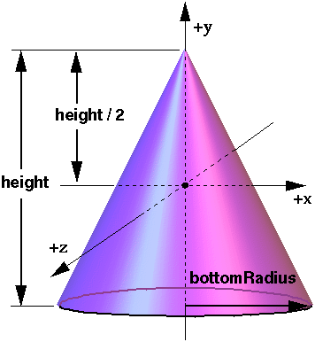
Cone : X3DGeometryNode {
  SFNode  [in,out] metadata     NULL [X3DMetadataObject]
  SFBool  []       bottom       TRUE
  SFFloat []       bottomRadius 1    (0,∞)
  SFFloat []       height       2    (0,∞)
  SFBool  []       side         TRUE
  SFBool  []       solid        TRUE
}
The Cone node specifies a cone which is centred in the local coordinate system and whose central axis is aligned with the local Y-axis. The bottomRadius field specifies the radius of the cone's base, and the height field specifies the height of the cone from the centre of the base to the apex. By default, the cone has a radius of 1.0 at the bottom and a height of 2.0, with its apex at y = height/2 and its bottom at y = -height/2. Both bottomRadius and height shall be greater than zero. Figure 13.2 illustrates the Cone node.
The side field specifies whether sides of the cone are created and the
bottom field specifies whether the bottom cap of the cone is created.
A value of TRUE specifies that this part of
the cone exists, while a value of FALSE specifies
that this part does not exist (not rendered or eligible for collision or sensor
intersection tests).
When a texture is applied to the sides of the cone, the texture wraps counterclockwise (from above) starting at the back of the cone. The texture has a vertical seam at the back in the X=0 plane, from the apex (0, height/2, 0) to the point (0, -height/2, -bottomRadius). For the bottom cap, a circle is cut out of the texture square centred at (0, -height/2, 0) with dimensions (2 × bottomRadius) by (2 × bottomRadius). The bottom cap texture appears right side up when the top of the cone is rotated towards the -Z-axis. TextureTransform affects the texture coordinates of the Cone (see 18.4.8 TextureTransform).
The solid field determines whether the cone is visible when viewed from the inside. 11.2.3 Common geometry fields provides a complete description of the solid field.
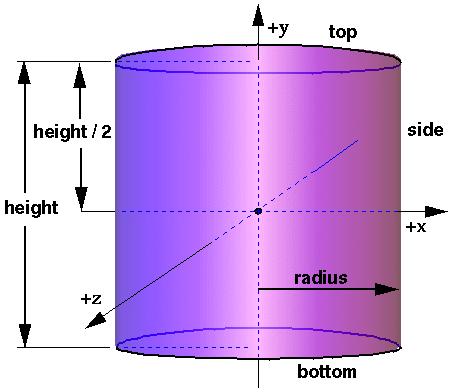
Cylinder : X3DGeometryNode {
  SFNode  [in,out] metadata NULL [X3DMetadataObject]
  SFBool  []       bottom   TRUE
  SFFloat []       height   2    (0,∞)
  SFFloat []       radius   1    (0,∞)
  SFBool  []       side     TRUE
  SFBool  []       solid    TRUE
  SFBool  []       top      TRUE
}
The Cylinder node specifies a capped cylinder centred at (0,0,0) in the local coordinate system and with a central axis oriented along the local Y-axis. By default, the cylinder is sized at "-1" to "+1" in all three dimensions. The radius field specifies the radius of the cylinder and the height field specifies the height of the cylinder along the central axis. Both radius and height shall be greater than zero. Figure 13.3 illustrates the Cylinder node.
The cylinder has three parts: the side, the
top (Y = +height/2)
and the bottom (Y = −height/2). Each part has an associated SFBool field that indicates whether the part exists (TRUE)
or does not exist (FALSE). Parts which do not
exist are not rendered and not eligible for intersection tests (EXAMPLE collision
detection or sensor activation).
When a texture is applied to a cylinder, it is applied differently to the sides, top, and bottom. On the sides, the texture wraps counterclockwise (from above) starting at the back of the cylinder. The texture has a vertical seam at the back, intersecting the X=0 plane. For the top and bottom caps, a circle is cut out of the unit texture squares centred at (0, ±height/2, 0) with dimensions 2 × radius by 2 × radius. The top texture appears right side up when the top of the cylinder is tilted toward the +Z-axis, and the bottom texture appears right side up when the top of the cylinder is tilted toward the −Z-axis. TextureTransform affects the texture coordinates of the Cylinder node (see 18.4.8 TextureTransform).
The solid field determines whether the cylinder is visible when viewed from the inside. 11.2.3 Common geometry fields provides a complete description of the solid field.
ElevationGrid : X3DGeometryNode {
  MFFloat [in]     set_height
  MFNode  [in,out] attrib          []   [X3DVertexAttributeNode]
  SFNode  [in,out] color           NULL [X3DColorNode]
  SFNode  [in,out] fogCoord        NULL [FogCoordinate]
  SFNode  [in,out] metadata        NULL [X3DMetadataObject]
  SFNode  [in,out] normal          NULL [X3DNormalNode]
  SFNode  [in,out] texCoord        NULL [X3DTextureCoordinateNode]
  SFBool  []       ccw             TRUE
  SFBool  []       colorPerVertex  TRUE
  SFFloat []       creaseAngle     0    [0,∞)
  MFFloat []       height          []   (-∞,∞)
  SFBool  []       normalPerVertex TRUE
  SFBool  []       solid           TRUE
  SFInt32 []       xDimension      0    [0,∞)
  SFFloat []       xSpacing        1.0  (0,∞)
  SFInt32 []       zDimension      0    [0,∞)
  SFFloat []       zSpacing        1.0  (0,∞)
}
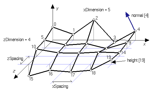
The ElevationGrid node specifies a uniform rectangular grid of varying height in the Y=0 plane of the local coordinate system. The geometry is described by a scalar array of height values that specify the height of a surface above each point of the grid.
The xDimension and zDimension fields indicate the number of elements of the grid height array in the X and Z directions. Both xDimension and zDimension shall be greater than or equal to zero. If either the xDimension or the zDimension is less than two, the ElevationGrid contains no quadrilaterals. The vertex locations for the rectangles are defined by the height field and the xSpacing and zSpacing fields:
Thus, the vertex corresponding to the point P[i, j] on the grid is placed at:
  P[i,j].x = xSpacing × i

  P[i,j].y = height[ i + j × xDimension]

  P[i,j].z = zSpacing × j

    where 0 ≤ i < xDimension and 0 ≤ j < zDimension,
    and P[0,0] is height[0] units above/below the origin of the local
    coordinate system
If the rendering algorithm being used requires tessellation, the quadrilaterals are split into triangles along the seam starting at the initial vertex of the quadrilateral and proceeding to the opposite vertex. The positive direction for the normal of each triangle shall be on the same side of the quadrilateral. The triangles are defined either counterclockwise or clockwise depending on the value of the ccw field.
EXAMPLE In Figure 13.4 with the ccw field set to TRUE, the first polygon is split into triangles with vertices [0, 5, 6] and vertices [0, 6, 1].
The set_height inputOnly field allows the height MFFloat field to be changed to support animated ElevationGrid nodes.
The color field specifies per-vertex or per-quadrilateral colours for
the ElevationGrid node depending on the value of colorPerVertex. If the
color field is NULL, the ElevationGrid
node is rendered with the overall attributes of the Shape node enclosing the ElevationGrid node (see 12 Shape component).
The colorPerVertex field determines whether colours specified in the
color field are applied to each vertex or each quadrilateral of the ElevationGrid
node. If colorPerVertex is FALSE and
the color field is not NULL, the color
field shall specify a node derived from
X3DColorNode containing at least (xDimension-1)×(zDimension-1)
colours; one for each quadrilateral, ordered as follows:
    QuadColor[i,j] = Color[ i + j × (xDimension-1)]

    where 0 ≤ i < xDimension-1 and 0 ≤ j < zDimension-1,
    and QuadColor[i,j] is the colour for the quadrilateral defined
    by height[i+j × xDimension], height[(i+1)+j × xDimension],
    height[(i+1)+(j+1) × xDimension] and height[i+(j+1) × xDimension]
If colorPerVertex is TRUE and the color
field is not NULL, the color field shall
specify a node derived from X3DColorNode containing at least xDimension × zDimension
colours, one for each vertex, ordered as follows:
    VertexColor[i,j] = Color[ i + j × xDimension ]

    where 0 ≤ i < xDimension and 0 ≤ j < zDimension,
    and VertexColor[i,j] is the colour for the vertex defined by
    height[ i+j × xDimension ]
The normal field specifies per-vertex or per-quadrilateral normals for
the ElevationGrid node. If the normal field is NULL,
the browser shall automatically generate normals, using the creaseAngle
field to determine if and how normals are smoothed across the surface
(see 11.2.3 Common
geometry fields).
The normalPerVertex field determines whether normals are applied to
each vertex or each quadrilateral of the ElevationGrid node depending on the
value of normalPerVertex. If normalPerVertex is FALSE
and the normal node is not NULL, the
normal field shall specify a node derived from
X3DNormalNode containing at least (xDimension−1)×(zDimension−1)
normals; one for each quadrilateral, ordered as follows:
    QuadNormal[i,j] = Normal[ i + j × (xDimension-1)]

    where 0 ≤ i < xDimension-1 and 0 ≤ j < zDimension-1,
    and QuadNormal[i,j] is the normal for the quadrilateral defined
    by height[i+j × xDimension], height[(i+1)+j × xDimension],
    height[(i+1)+(j+1) × xDimension] and height[i+(j+1) × xDimension]
If normalPerVertex is TRUE and the normal
field is not NULL, the normal field
shall specify a node derived from X3DNormalNode containing at least
xDimension × zDimension
normals; one for each vertex, ordered as follows:
    VertexNormal[i,j] = Normal[ i + j × xDimension]

    where 0 ≤ i < xDimension and 0 ≤ j < zDimension,
    and VertexNormal[i,j] is the normal for the vertex defined
    by height[i+j × xDimension]
The texCoord field specifies per-vertex texture coordinates for the
ElevationGrid node. If texCoord is NULL,
default texture coordinates are applied to the geometry. The default texture
coordinates range from (0,0) at the first vertex to (1,1) at the last vertex.
The S texture coordinate is aligned with the positive X-axis, and the T texture
coordinate with positive Z-axis. If texCoord is not NULL, it shall specify
a node derived from
X3DTextureCoordinateNode containing at least (xDimension)×(zDimension)
texture coordinates; one for each vertex, ordered as follows:
    VertexTexCoord[i,j] = TextureCoordinate[ i + j × xDimension]

    where 0 ≤ i < xDimension and 0 ≤ j < zDimension,
    and VertexTexCoord[i,j] is the texture coordinate for the vertex
    defined by height[i+j × xDimension]
The ccw, solid, and creaseAngle fields are described in 11.2.3 Common geometry fields.
By default, the quadrilaterals are defined with a counterclockwise ordering.
Hence, the Y-component of the normal is positive. Setting the ccw field
to FALSE reverses the normal direction. Backface
culling is enabled when the solid field is TRUE.
See Figure 13.4 for a depiction of the ElevationGrid node.
Extrusion : X3DGeometryNode {
  MFVec2f    [in]     set_crossSection
  MFRotation [in]     set_orientation
  MFVec2f    [in]     set_scale
  MFVec3f    [in]     set_spine
  SFNode     [in,out] metadata         NULL                      [X3DMetadataObject]
  SFBool     []       beginCap         TRUE
  SFBool     []       ccw              TRUE
  SFBool     []       convex           TRUE
  SFFloat    []       creaseAngle      0                         [0,∞)
  MFVec2f    []       crossSection     [1 1 1 -1 -1 -1 -1 1 1 1] (-∞,∞)
  SFBool     []       endCap           TRUE
  MFRotation []       orientation      0 0 1 0                   [-1,1] or (-∞,∞)
  MFVec2f    []       scale            1 1                       (0,∞)
  SFBool     []       solid            TRUE
  MFVec3f    []       spine            [0 0 0 0 1 0]             (-∞,∞)
}
The Extrusion node specifies geometric shapes based on a two dimensional cross-section extruded along a three dimensional spine in the local coordinate system. The cross-section can be scaled and rotated at each spine point to produce a wide variety of shapes.
An Extrusion node is defined by:
Shapes are constructed as follows. The cross-section curve, which starts as a curve in the Y=0 plane, is first scaled about the origin by the first scale parameter (first value scales in X, second value scales in Z). It is then translated by the first spine point and oriented using the first orientation parameter (as explained later). The same procedure is followed to place a cross-section at the second spine point, using the second scale and orientation values. Corresponding vertices of the first and second cross-sections are then connected, forming a quadrilateral polygon between each pair of vertices. This same procedure is then repeated for the rest of the spine points, resulting in a surface extrusion along the spine.
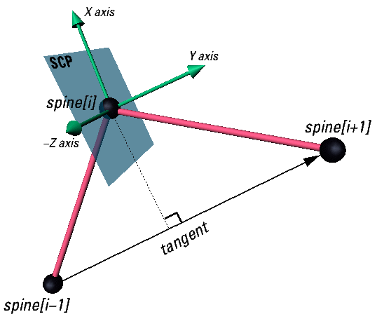
The final orientation of each cross-section is computed by first orienting it relative to the spine segments on either side of point at which the cross-section is placed. This is known as the spine-aligned cross-section plane (SCP), and is designed to provide a smooth transition from one spine segment to the next (see Figure 13.5). The SCP is then rotated by the corresponding orientation value. This rotation is performed relative to the SCP. For example, to impart twist in the cross-section, a rotation about the Y-axis (0 1 0) would be used. Other orientations are valid and rotate the cross-section out of the SCP.
The SCP is computed by first computing its Y-axis and Z-axis, then taking the cross product of these to determine the X-axis. These three axes are then used to determine the rotation value needed to rotate the Y=0 plane to the SCP. This results in a plane that is the approximate tangent of the spine at each point, as shown in Figure 13.5. First the Y-axis is determined, as follows:
Let n be the number of spines and let i be the index variable
satisfying
0 ≤ i < n:
The Z-axis is determined as follows:
Z = (spine[i+1] − spine[i]) × (spine[i-1] − spine[i])
Z = (spine[1] − spine[0]) × (spine[n-2] − spine[0])
Once the Y- and Z-axes have been computed, the X-axis can be calculated as their cross-product.
If the number of scale or orientation values is greater than the number of spine points, the excess values are ignored. If they contain one value, it is applied at all spine points. The results are undefined if the number of scale or orientation values is greater than one but less than the number of spine points. The scale values shall be positive.
If the three points used in computing the Z-axis are collinear, the cross-product is zero so the value from the previous point is used instead.
If the Z-axis of the first point is undefined (because the spine is not closed and the first two spine segments are collinear) then the Z-axis for the first spine point with a defined Z-axis is used.
If the entire spine is collinear, the SCP is computed by finding the rotation of a vector along the positive Y-axis (v1) to the vector formed by the spine points (v2). The Y=0 plane is then rotated by this value.
If two points are coincident, they both have the same SCP. If each point has a different orientation value, then the surface is constructed by connecting edges of the cross-sections as normal. This is useful in creating revolved surfaces.
Note: combining coincident and non-coincident spine segments, as well as other combinations, can lead to interpenetrating surfaces which the extrusion algorithm makes no attempt to avoid.
The following common cases are among the effects which are supported by the Extrusion node:
Extrusion has three parts: the sides, the beginCap (the surface
at the initial end of the spine) and the endCap (the surface at the final
end of the spine). The caps have an associated SFBool field that indicates whether
each exists (TRUE) or doesn't exist (FALSE).
When the beginCap or endCap fields are specified as TRUE,
planar cap surfaces will be generated regardless of whether the crossSection
is a closed curve. If crossSection is not a closed curve, the caps are
generated by adding a final point to crossSection that is equal to the
initial point. An open surface can still have a cap, resulting (for a simple
case) in a shape analogous to a soda can sliced in half vertically. These surfaces
are generated even if spine is also a closed curve. If a field value
is FALSE, the corresponding cap is not generated.
Texture coordinates are automatically generated by Extrusion nodes. Textures are mapped so that the coordinates range in the U direction from 0 to 1 along the crossSection curve (with 0 corresponding to the first point in crossSection and 1 to the last) and in the V direction from 0 to 1 along the spine curve (with 0 corresponding to the first listed spine point and 1 to the last). If either the endCap or beginCap exists, the crossSection curve is uniformly scaled and translated so that the larger dimension of the cross-section (X or Z) produces texture coordinates that range from 0.0 to 1.0. The beginCap and endCap textures' S and T directions correspond to the X and Z directions in which the crossSection coordinates are defined.
The browser shall automatically generate normals for the Extrusion node, using the creaseAngle field to determine if and how normals are smoothed across the surface. Normals for the caps are generated along the Y-axis of the SCP, with the ordering determined by viewing the cross-section from above (looking along the negative Y-axis of the SCP). By default, a beginCap with a counterclockwise ordering shall have a normal along the negative Y-axis. An endCap with a counterclockwise ordering shall have a normal along the positive Y-axis.
Each quadrilateral making up the sides of the extrusion are ordered from the bottom cross-section (the one at the earlier spine point) to the top. So, one quadrilateral has the points:
    spine[0](crossSection[0], crossSection[1])
    spine[1](crossSection[1], crossSection[0])
in that order. By default, normals for the sides are generated as described in 13.2.2 Shape and geometry nodes.
For instance, a circular crossSection with counter-clockwise ordering and the
default spine form a cylinder. With solid TRUE
and ccw TRUE, the cylinder is visible
from the outside. Changing ccw to FALSE
makes it visible from the inside.
The ccw, solid, convex, and creaseAngle fields are described in 11.2.3 Common geometry fields.
IndexedFaceSet : X3DComposedGeometryNode {
  MFInt32 [in]     set_colorIndex
  MFInt32 [in]     set_coordIndex
  MFInt32 [in]     set_normalIndex
  MFInt32 [in]     set_texCoordIndex
  MFNode  [in,out] attrib            []   [X3DVertexAttributeNode]
  SFNode  [in,out] color             NULL [X3DColorNode]
  SFNode  [in,out] coord             NULL [X3DCoordinateNode]
  SFNode  [in,out] fogCoord          NULL [FogCoordinate]
  SFNode  [in,out] metadata          NULL [X3DMetadataObject]
  SFNode  [in,out] normal            NULL [X3DNormalNode]
  SFNode  [in,out] texCoord          NULL [X3DTextureCoordinateNode]
  SFBool  []       ccw               TRUE
  MFInt32 []       colorIndex        []   [0,∞) or -1
  SFBool  []       colorPerVertex    TRUE
  SFBool  []       convex            TRUE
  MFInt32 []       coordIndex        []   [0,∞) or -1
  SFFloat []       creaseAngle       0    [0,∞)
  MFInt32 []       normalIndex       []   [0,∞) or -1
  SFBool  []       normalPerVertex   TRUE
  SFBool  []       solid             TRUE
  MFInt32 []       texCoordIndex     []   [-1,∞)
}
The IndexedFaceSet node represents a 3D shape formed by constructing faces (polygons) from vertices listed in the coord field. The coord field contains a Coordinate node that defines the 3D vertices referenced by the coordIndex field. IndexedFaceSet uses the indices in its coordIndex field to specify the polygonal faces by indexing into the coordinates in the Coordinate node. An index of "−1" indicates that the current face has ended and the next one begins. The last face may be (but does not have to be) followed by a "−1" index. If the greatest index in the coordIndex field is N, the Coordinate node shall contain N+1 coordinates (indexed as 0 to N). Each face of the IndexedFaceSet shall have:
Otherwise, The results are undefined.
The IndexedFaceSet node is specified in the local coordinate system and is affected by the transformations of its ancestors.
Descriptions of the coord, normal, and texCoord fields are provided in Coordinate, X3DNormalNode, and X3DTextureCoordinateNode, respectively.
Details on lighting equations and the interaction between color field, normal field, textures, materials, and geometries are provided in 11 Rendering component and 12 Shape component.
If the color field is not NULL, it shall
contain a node derived from
X3DColorNode whose colours are applied to the vertices or faces of the
IndexedFaceSet as follows:
If the color field is NULL, the geometry
shall be rendered normally using the Material and texture defined in the Appearance
node (see 12 Shape component for details).
If the normal field is not NULL, it
shall contain a node derived from X3DNormalNode whose normals are applied to the vertices or faces
of the IndexedFaceSet in a manner exactly equivalent to that described above
for applying colours to vertices/faces (where normalPerVertex corresponds
to colorPerVertex and normalIndex corresponds to colorIndex).
If the normal field is NULL, the browser
shall automatically generate normals, using creaseAngle to determine
if and how normals are smoothed across shared vertices (see 11.2.3 Common
geometry fields).
If the texCoord field is not NULL, it
shall contain a node derived from X3DTextureCoordinateNode. The texture coordinates in that node
are applied to the vertices of the IndexedFaceSet as follows:
If the texCoord field is NULL, a default
texture coordinate mapping is calculated using the local coordinate system bounding
box of the shape. The longest dimension of the bounding box defines the S coordinates,
and the next longest defines the T coordinates. If two or all three dimensions
of the bounding box are equal, ties shall be broken by choosing the X, Y, or
Z dimension in that order of preference. The value of the S coordinate ranges
from 0 to 1, from one end of the bounding box to the other. The T coordinate
ranges between 0 and the ratio of the second greatest dimension of the bounding
box to the greatest dimension.
Figure
13.6 illustrates the default texture coordinates for a simple box shaped
IndexedFaceSet with an X dimension twice as large as the Z dimension and four
times as large as the Y dimension.
Figure 13.7
illustrates the original texture image used on the IndexedFaceSet
used in Figure
13.6.
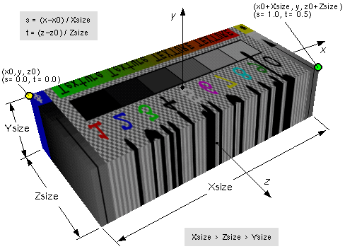
Figure 13.6 — IndexedFaceSet texture default mapping
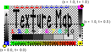
Figure 13.7 — ImageTexture for IndexedFaceSet in Figure 13.6
11.2.3 Common geometry fields, provides a description of the ccw, solid, convex, and creaseAngle fields.
Sphere : X3DGeometryNode {
  SFNode  [in,out] metadata NULL [X3DMetadataObject]
  SFFloat []       radius   1    (0,∞)
  SFBool  []       solid    TRUE
}
The Sphere node specifies a sphere centred at (0, 0, 0) in the local coordinate system. The radius field specifies the radius of the sphere and shall be greater than zero. Figure 13.8 depicts the fields of the Sphere node.
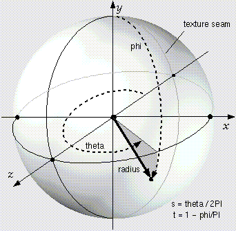
When a texture is applied to a sphere, the texture covers the entire surface, wrapping counterclockwise from the back of the sphere (i.e., longitudinal arc intersecting the -Z-axis) when viewed from the top of the sphere. The texture has a seam at the back where the X=0 plane intersects the sphere and Z values are negative. TextureTransform affects the texture coordinates of the Sphere (see 18.4.8 TextureTransform).
The solid field determines whether the sphere is visible when viewed from the inside. 11.2.3 Common geometry fields provides a complete description of the solid field.
The Geometry3D component provides three levels of support as specified in Table 13.2. Level 1 provides the basic indexed geometry types with limited support for some fields, as well as the geometric primitives and the Shape node. Level 2 adds support for the IndexedFaceSet node. Level 3 adds support for the ElevationGrid node to enable lightweight terrain and data visualization and supports all fields in all nodes supported at Level 3. Level 4 adds support for the Extrusion node.
Table 13.2 — Geometry3D component support levels
| Level | Prerequisites | Nodes/Features | Support |
|---|---|---|---|
| 1 | Core 1 Grouping 1 Rendering 1 Shape 1 |
||
| Box | All fields fully supported. | ||
| Cone | All fields fully supported. | ||
| Cylinder | All fields fully supported. | ||
| Sphere | All fields fully supported. | ||
| 2 | Core 1 Grouping 1 Rendering 1 Shape 1 |
||
| All Level 1 geometry nodes | All fields as supported in Level 1. | ||
| IndexedFaceSet | ccw optionally supported. set_colorIndex optionally
supported. set_normalIndex optionally supported. normal
optionally supported. Only convex indexed face sets supported. Hence, convex
optionally supported. For creaseAngle, only 0 and
π
radians supported (or the equivalent if a different angle base unit
has been specified). normalIndex optionally supported. Face list shall be well-defined as follows:
|
||
| 3 | Core 1 Grouping 1 Rendering 1 Shape 1 |
||
| All Level 2 geometry nodes | All fields as supported in Level 2. | ||
| ElevationGrid | ccw optionally supported. | ||
| 4 | Core 1 Grouping 1 Rendering 1 Shape 1 |
||
| All Level 3 geometry nodes | All fields fully supported. | ||
| Extrusion | All fields fully supported. |
![]()