Part 2: Humanoid animation (HAnim) motion data animation
4 Concepts
Part 2: Humanoid animation (HAnim) motion data animation
4 Concepts
 4.1 General
This clause describes the concepts that specify how motion data, including motion-capture data, is used to animate HAnim figures.
Table 4.1 lists the topics for this clause.
The following conventions are used throughout this document:
Italics are used for field names, and are also used when new terms are introduced and equation variables are referenced.
A fixed-space font is used for source code examples.
Object names are appropriately capitalized (e.g., "The Motion object is a ...") and are represented in Bold face font.
Throughout this document, references to external documents in the bibliography are denoted using the "[ABCD]" notation.
EXAMPLE [ABCD] refers to a reference described in the Bibliography.
All length measurements in this document are in metres. All angle measurements are in radians.
All rotations are specified as a rotation axis and an angle (e.g., 1 0 0 π).
Numeric entries representing field values use decimal points (rather than decimal commas) in order to remain syntactically correct.
4.2 Introduction to animation using motion dataThis clause specifies basic concepts of humanoid animation and an overall procedure for defining humanoid animation using an HAnim model and motion data. Motion parameters necessary for generating humanoid animation are defined. Humanoid animation data is organized using these parameters and the geometric data of a humanoid model. The animation data defines motion for a humanoid model obtained using various graphics tools or scanning devices. Motion data generated using an animation algorithm or obtained using a motion-capture device can be used to define humanoid animation data and to generate humanoid animation sequences. The humanoid animation data can be exchanged through networks of heterogeneous computer systems and between different applications.
4.3 Humanoid animation dataHumanoid animation is generated by modelling and animating humanoid geometrical objects. Modelling is the process of producing a geometrical definition of a humanoid object which may be used in a scene. The manner in which data for modelling HAnim figures is created is specified in ISO/IEC 19774-1. General animation data can be obtained from motion-capture devices and/or animation algorithms. This clause specifies how to integrate humanoid models and animation data that are usable by different applications and/or HAnim figures.
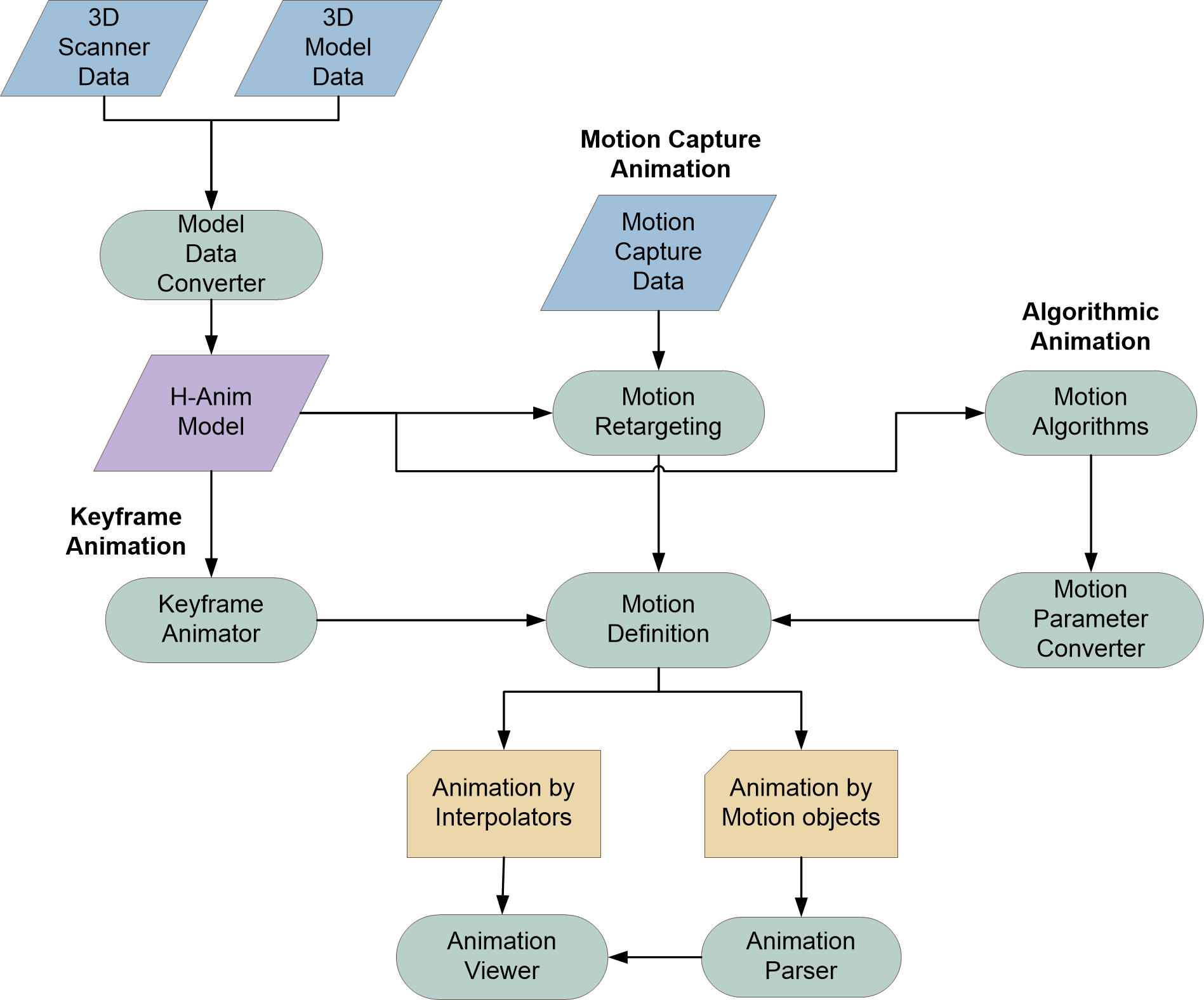
Figure 4.1 shows the overall procedure for generating and storing HAnim humanoid animation sequences using motion-capture data, keyframe animation, and algorithmic animation methods including kinematics and dynamics. The sequences may then be transferred and exchanged through different computing and application environments. The motion of an HAnim humanoid model designed by one graphics tool can be applied as the motion for a character designed by a different graphics tool.
Figure 4.1 — Procedure of humanoid animation
An HAnim humanoid model can be generated using general graphics tools and 3D scanner data. Conversion from raw 3D humanoid models into HAnim models is required if the graphics modelling tools and the 3D scanners do not support the explicit generation of HAnim humanoid models. The HAnim models are specified according to ISO/IEC 19774-1. The motion of an HAnim character can be produced from motion-capture data, keyframe parameters, and/or motion parameters for other motion algorithms.
The motion definition process in Figure 4.1 represents the definition of the animation encoding to be applied to the HAnim model. The animation encoding may take the form of interpolators, specified in Clause 5 HAnim motion data using interpolators, or Motion objects, specified in Clause 6 HAnim motion data animation using Motion objects.
HAnim keyframe animation is generated by an HAnim 19774-1 humanoid model, keyframe parameters, and an interpolation process. Transformation parameters used for generating an animation sequence are obtained by interpolating between the keyframe parameters. These parameters can be used to specify either interpolators or a Motion object for the animation.
HAnim motion-capture animation is generated by an HAnim 19774-1 humanoid model and motion-capture data. A joint mapping procedure between the HAnim model and the motion-capture figure may be necessary to obtain parameter values for corresponding joints. During the joint mapping procedure, motion retargeting may also be used to adapting an animated motion from one character to another. A Motion object for HAnim motion-capture animation is specified by motion-capture frames data and frame information, or the data is converted for use by interpolators.
HAnim algorithmic animation is generated by an HAnim 19774-1 humanoid model and transformation parameters obtained by various animation algorithms such as forward kinematics, inverse kinematics (IK) or dynamics. Regardless of which algorithms are used, motion can be specified by transformation parameters necessary for generating animation sequences using interpolators. A Motion object for HAnim algorithmic animation can also be specified by the transformation parameters for each frame.
4.4 HAnim joint
mapping for motion-capture animationHumanoid animation data is specified as an exchangeable data format that can be used between applications, between tools, between systems or between platforms. The data includes humanoid geometry and animation parameters that allow any application to produce the same humanoid animation. The humanoid geometry is the term used for the geometrical data definitions of all humanoid objects in a scene. The animation parameters are used for generating animation sequences with the geometry. The humanoid model can be prepared as specified in ISO/IEC 19774-1. It consists of segments and joints that specify the hierarchy of a humanoid skeleton. A Segment is represented by a geometry object, and a Joint connects two segments according to the hierarchy. The number and the location of joints are determined during a rigging process when generating a humanoid model. motion-capture data is obtained via motion sensors attached to the joints of a real person enacting the animation (the motion-capture figure). Generally, the number and the location of the motion sensors, as well as the joint hierarchies differ depending on the motion-capture device. Therefore, a joint mapping process is required to obtain motion parameters for each HAnim Joint.
Non-human humanoids can also be represented with their joints and segments similarly to human humanoids, and their motion-capture animation can be generated depending on their specified hierarchy. However, for non-human humanoids, the number of joints and segments may differ and levels of articulation are not specified.
There are several levels of articulation for human models specified in ISO/IEC 19774-1 that can be used when representing human geometry, depending on the number of joints needed to represent the human. ISO/IEC 19774-1 specifies five LOA models, namely LOA‑0, LOA‑1, LOA‑2, LOA‑3, and LOA‑4. Each level of articulation adds more joints and segments providing increasingly greater detail. Table 4.2 shows a comparison of the levels of articulation.
Table 4.2 — Representation details for each level of articulation (LOA)
| LOA‑0 | LOA‑1 | LOA‑2 | LOA‑3 | LOA‑4 | |
|---|---|---|---|---|---|
| Number of joints | 1 | 18 | 71 (23 + 40 hand joints + 8 foot joints) |
94 (46 + 40 hand joints + 8 foot joints) |
146 (46 + 48 hand joints + 52 foot joints) |
| Number of segments | 1 | 18 | 71 (23 + 40 hand segments + 8 foot segments) |
94 (46 + 40 hand segments + 8 foot segments) |
146 (46 + 48 hand segments + 52 foot segments) |
| Representation details | No articulation | Basic human skeleton joints | Addition of more spine joints than LOA‑1, more finger joints and foot joints | Addition of more spine joints than LOA‑2, more facial joints | Eight more joints than LOA‑3 for hands, 44 more joints for feet |
The articulation for non-human HAnim figures is specified by the modeller. The default position of non-human HAnim figures is that which occurs when all transformations are zero. This clause specifies how motion data can be consistently applied to segments and joints for motion-capture animation.
When generating motion data animation for an HAnim figure, each Joint of the HAnim figure shall be mapped to the corresponding joint of the motion capture figure. Through this process, each HAnim Joint receives the values of the corresponding motion parameters from the motion-capture figure. Depending on the motion-capture device, joint names and numbers may be different from those defined for the HAnim model.
Ideally, corresponding joint names and numbers shall be the same for the HAnim model and the motion-capture figure. If the names differ, the names of the motion-capture figure shall be converted to match the Joint names of the HAnim figure. Segment names shall also be treated in the same way.
If the HAnim figure has more joints than the motion-capture figure, an unmapped Joint that includes child joints shall have the same motion parameters as the parent Joint of the HAnim figure. Thus, there is no transformation at the unmapped joints except transformation by their parent joints. If the HAnim figure has an equal number of joints to that of the motion-capture figure, each Joint of the HAnim model receives transformation parameters from the corresponding joint of the motion-capture figure. A mapping process may also be needed if joint names and locations are different between the HAnim figure and the motion-capture figure even though the number of joints is equal. If the HAnim figure has fewer joints than the motion-capture figure, only mapped joints of the motion-capture figure are used for generating the animation of the HAnim figure. Unmapped joints of the motion-capture figure shall not be used. Even when the number of joints is the same between the HAnim figure and the motion-capture figure, joint names and positions may not be. In this case, joint mapping shall be done so that each joint of the motion-capture figure is mapped to the corresponding Joint of the HAnim figure.
An LOA‑1 data structure, represented by the hierarchy specified in ISO/IEC 19774-1, contains 18 joint name:segment name pairs. Each segment has a joint that is a centre (pivot) point for rotational transformation. The root segment has a centre point for translational and rotational transformation. Each segment has its own geometric data, such as a mesh or a set of polygons. Therefore, 18 centres shall be defined for the LOA‑1 hierarchy in HAnim.
The left half of Table 4.3 shows an example of LOA‑1
joint mapping where the number of joints is the same but joint names and
positions differ slightly. The second column shows LOA‑1 HAnim
joints, and the third column shows an example of motion-capture joints. For
mapping no. 1, the motion-capture Hips joint is mapped to the
HAnim humanoid_root. This means that motion-capture parameter
values for the Hips joint are used for the transformation of
the humanoid_root joint for the HAnim model. For mapping no.
6, the l_midtarsal joint of the HAnim model has no
transformation values from the motion-capture figure because there is no
corresponding joint. For mapping no. 13, one of the two joints,
LeftCollar and LeftShoulder, is mapped to the
l_shoulder joint of the HAnim model. If
Leftshoulder is mapped to l_shoulder, the motion
parameters of LeftCollar are not used for the HAnim model.
Clause A.1 shows the motion-capture data
used in the left half of Table 4.3.
Right half of Table 4.3 illustrates a case of an
LOA‑1 HAnim model and a 21-joint motion-capture figure model. The
motion-capture figure has three more joints for ankle and one more joint for
vertebrae compared to the left half of Table 4.3. For mapping
no. 11, one of the two joints, Chest and Chest2,
is mapped to the vl5 joint of the HAnim model. Other joints are
mapped to the HAnim model as in the left half of Table 4.3.
Clause A.2 shows the motion-capture data
used in the right half of Table 4.3.
Joint mapping for the other LOAs shall be performed analogously.
Table 4.3 — LOA‑1 joint mapping examples
4.5 Composition of motion-capture dataGenerally, motion-capture data consists of two portions. The first portion contains a hierarchical humanoid joint structure, the number of channels, and the channels. The number of channels references the number of transformation types, such as translation-x, translation-y, translation-z, rotation-x, rotation-y, and rotation-z. Channels include transformation types used for capturing data from a motion-capture device. This portion is mapped into the HAnim modelling portion for HAnim motion-capture animation using joint mapping between the motion-capture structure and the HAnim hierarchy. The level of articulation is selected based on the complexity of the motion-capture structure. The second portion has motion parameter values for channels for all joints, as well as the number of frames and frame time for a frame display.
4.6 Transformation of HAnim motion-capture animationIn order to generate animation at each Joint, each Segment of an HAnim model is processed with translational and/or rotational transformation. The root Segment of the HAnim has basic translational and rotational transformation. The other segments have rotational transformation at their joints. All transformations are accomplished according to the hierarchy of each LOA. Other transformations can also be applied to the Joint objects.
Transformation for motion-capture animation is processed as follows:
humanoid_root Joint shall have translational and
rotational parameter values.humanoid_root Joint),
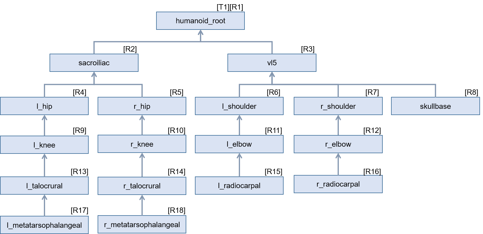
rotational parameter values are applied.For example, in the case of LOA‑1 transformation, each Joint has the following transformation supposing only translation and rotation for each Joint (Figure 4.2). [T1] and [R1] denote translation and rotation respectively. It is assumed that [T1] and [R1] are 4 x 4 homogeneous transformation matrices typically used in computer graphics.
humanoid_root Joint has the motion of [T1] and [R1]
transformations. Then, the motion is calculated by [T1]×[R1].
According to the tree structure, all its descendent joints have the
transformation [T1]×[R1] applied.sacroiliac Joint has the motion of [R2] transformation.
Then, the motion is calculated by [T1]×[R1]×[R2]. According to
the tree structure, all its descendent joints have the transformation [R2]
applied.vl5 Joint has the motion of [R3] transformation. Then,
the motion is calculated by [T1]×[R1]×[R3]. According to the
tree structure, all its descendent joints have the transformation [R3]
applied.l_hip Joint has the motion of [R4] transformation. Then,
the motion is calculated by [T1]×[R1]×[R2]×[R4].
According to the tree structure, all its descendent joints have the
transformation [R4] applied.r_hip Joint has the motion of [R5] transformation. Then,
the motion is calculated by [T1]×[R1]×[R2]×[R5].
According to the tree structure, all its descendent joints have the
transformation [R5] applied.l_shoulder Joint has the motion of [R6] transformation.
Then, the motion is calculated by [T1]×[R1]×[R3]×[R6].
According to the tree structure, all its descendent joints have the
transformation [R6] applied.r_shoulder Joint has the motion of [R7] transformation.
Then, the motion is calculated by [T1]×[R1]×[R3]×[R7].
According to the tree structure, all its descendent joints have the
transformation [R7] applied.skullbase Joint has the motion of [R8] transformation.
Then, the motion is calculated by [T1]×[R1]×[R3]×[R8].
This is a leaf Joint in the tree structure. [R8] transformation is applied
only to this Joint.l_knee Joint has the motion of [R9] transformation. Then,
the motion is calculated by [T1]×[R1]×[R2]×[R4]×[R9].
According to the tree structure, all its descendent joints have the
transformation [R9] applied.r_knee Joint has the motion of [R10] transformation. Then,
the motion is calculated by [T1]×[R1]×[R2]×[R5]×[R10].
According to the tree structure, all its descendent joints have the
transformation [R10] applied.l_elbow Joint has the motion of [R11] transformation.
Then, the motion is calculated by
[T1]×[R1]×[R3]×[R6]×[R11]. According to the tree
structure, all its descendent joints have the transformation [R11] applied.r_elbow Joint has the motion of [R12] transformation.
Then, the motion is calculated by
[T1]×[R1]×[R3]×[R7]×[R12]. According to the tree
structure, all its descendent joints have the transformation [R12] applied.l_talocrural Joint has the motion of [R13]
transformation. Then, the motion is calculated by
[T1]×[R1]×[R2]×[R4]×[R9]×[R13]. According to
the tree structure, all its descendent joints have the transformation [R13]
applied.r_talocrural Joint has the motion of [R14]
transformation. Then, the motion is calculated by
[T1]×[R1]×[R2]×[R5]×[R10]×[R14]. According to
the tree structure, all its descendent joints have the transformation [R14]
applied.l_radiocarpal Joint has the motion by [R15]
transformation. Then, the motion is calculated by
[T1]×[R1]×[R3]×[R6]×[R11]×[R15]. This is a
leaf Joint in the tree structure. [R15] transformation is applied only to
this Joint.r_radiocarpal Joint has the motion by [R16]
transformation. Then, the motion is calculated by
[T1]×[R1]×[R3]×[R7]×[R12]×[R16]. This is a
leaf Joint in the tree structure. [R16] transformation is applied only to
this Joint.l_metatarsophalangeal Joint has the motion of [R17]
transformation. Then, the motion is calculated by
[T1]×[R1]×[R2]×[R4]×[R9]×[R13]×[R17].
This is a leaf Joint in the tree structure. [R17] transformation is applied
only to this Joint.r_metatarsophalangeal Joint has the motion of [R18]
transformation. Then, the motion is calculated by
[T1]×[R1]×[R2]×[R5]×[R10]×[R14]×[R18].
This is a leaf Joint in the tree structure. [R18] transformation is applied
only to this Joint.
4.7 HAnim animation data for keyframe animationHumanoid animation data shall include how to transform Segment and Joint objects at each time that comprises an animated humanoid figure. At each instant of time, the motion of a Joint determines the geometrical transformation of a segment. In the modelling of a humanoid, a Joint is attached to a Segment, and then the segment shall be transformed together with the joint’s motion. Therefore, humanoid animation results from representing each joint’s change of position and orientation with its segment geometry while maintaining the hierarchy of all the joints of the humanoid.
The transformation values can be exchanged between humanoids designed with different graphics tools or applications, and if the levels of articulation are equal between the figures, the same motion can be obtained for the figures. The values consist of transformation parameter types and their values necessary for generating motion at each joint. In addition to HAnim modelling data, HAnim animation data that includes all these values can be transferred between applications.
A full example is included in Annex B.
4.8 HAnim animation definition for motion
capture animationWhen generating HAnim motion data animation, motion-capture data obtained through each motion sensor attached to a joint can be used to define the motion of each joint. Each Joint object shall include all motion parameters and their captured values at each instance of time of motion. HAnim motion data shall include time duration for animation, number of frames, number of parameters for motion, and parameter values for motion for all joints in the HAnim hierarchy depending on the level of articulation. Then, a Segment object, usually including geometrical data for transformation, is transformed according to the parameters and their values.
There are two methods of defining motion-capture animation data for HAnim characters. One is to use interpolators. When using interpolators for defining motion-capture data, the following shall be specified in addition to HAnim modelling data:
To specify motion-capture parameters for an HAnim model, the parameters shall be transformed as required by the output of the interpolators. The conversion of motion-capture data to interpolators is described in Clause 5 HAnim motion data animation using interpolators.
Clause 5.4 Excerpted example of interpolator animation shows an excerpted example specifying motion data animation using X3D Interpolator nodes. A full example is included in Annex C.
The other method to define motion-capture animation data for an HAnim model is to specify a Motion object. The Motion object consists of frame information, joint mapping information and motion-capture parameter values for all frames.
Frame information specifies the following:
The joint mapping information specifies corresponding Joint and motion capture channel information of motion-capture data for the HAnim figure. It includes the following:
Xtranslation, Ytranslation,
Ztranslation, Xrotation, Yrotation,
and Zrotation. Channels denote ordered transformation types
such as "Zrotation, Xrotation,
Yrotation".The motion-capture parameter values specify all parameter values for motion-capture channels for each corresponding Joint of the HAnim model. It includes the following:
Xtranslation, Ytranslation,
Ztranslation, and rotational parameter values from three
rotational channels such as Xrotation, Yrotation,
and Zrotation. The root Joint has three translational
parameter values and three rotational parameter values, while all the
other joints have three rotational parameter values.6.6 Example Usage of Motion object shows an excerpted example of specifying motion-capture animation using Joint and Motion objects in an X3D context. A full description of this example is included in Annex D.