3 Definitions
After updating Clause 6, replace the references to subclauses in Clause 6 with new references to the newly renumbered subclauses.
Alphabetically insert the following definitions in Clause 3 and renumber the subclauses:
"3.xx Earth reference model (ERM)
One of the models available with this specification of either the physical surface of the Earth (usually in the form of an oblate spheroid) or a gravity equipotential surface for the Earth (often called a geoid).
3.xx Free Form Deformation (FFD)
T he result of transforming the control points of a piece of NURBS geometry.
3.xx geocentric spatial reference frame (GC or GCC)
A spatial reference frame in which an arbitrary point location of the surface of the Earth is determined by (x,y,z) parameters in metres from the origin (Earth centre), where X-axis is aligned with the Prime (Greenwich) Meridian in the Equatorial plane, Z-axis is aligned with polar axis (coincident with the Earth’s rotational axis) pointing North, and Y-axis is defined as orthogonal to the other two such as to form a right handed orthogonal set.
3.xx geodetic spatial reference frame (GD or GDC)
A spatial reference frame defined using two angular measures called latitude and longitude and a linear height measure from the surface of the ERM, where:
-
latitude is specified in degrees in the range [–90, +90];
-
longitude is specified in degrees in either the range [–180, +180] or the range [0, +360] where zero degrees represents the same longitude in either range;
-
linear height is measured in metres positive above the reference surface.
-
the origin is at a specified point near Greenwich, United Kingdom.
3.xx geoid
A surface along which the gravity potential is everywhere equal, and to which the direction of gravity is always perpendicular at that surface. The Earth's geoid coincides with that surface to which the oceans would conform over the entire Earth, if free to adjust to the combined effect of the Earth's mass attraction and the centrifugal force of the Earth's rotation, which is roughly equivalent to the undisturbed mean sea level.
3.xx georeferenced local coordinate system
A local coordinate system in which the origin is fixed to a specified geospatial location and specified axis orientation. Such coordinate systems are used in this International Standard to associate models with positions on the Earth.
3.xx NURBS
Non-Uniform Rational B-spline. This may be either a curve or a surface.
3.xx spatial reference frame
The combination of a specific coordinate system that is associated with a specified point in relation to a reference object defined by a model of that reference object. For this International Standard, the reference object is always the Earth (see Earth reference model).
3.xx trimmed NURBS surface
A closed combination of 2D NURBS curves and/or piecewise linear line segments that is used to define the areas of validity and invalidity of a NURBS surface.
3.xx trimming loop
A NURBS surface defined with one or more trimming loops.
3.xx universal transverse mercator (UTM) spatial reference frame
A spatial reference frame in which the result of the UTM projection is augmented by a linear height measured from the surface of the ERM. The northing, easting, and elevation values are specified relative to a fixed zone and hemisphere.
3.xx universal transverse mercator (UTM) projection
A projection of an ellipsoid (that represents the Earth) to a cylinder, in which the cylinder and the ellipsoid are tangent along a meridian, and a point on the ellipsoid is projected on the surface of the cylinder which is opened and flattened such that the ellipsoid is divided into 60 zones each six degrees wide in longitude. UTM is never used for locations above 84.0 degrees North and 80.0 degrees South since the error resulting from the projection is considered too severe. The longitudinal value is called the easting and the latitudinal value is called the northing.
3.xx VRML coordinate system
A rectangular Cartesian coordinate system with arbitrary origin used to define VRML geometry."
Pages 19 through 61
4 Concepts
After updating Clause 6, replace the references to subclauses in Clause 6 with new references to the newly renumbered subclauses.
Page 20
Table 4.1
Append the following text to the Table of contents and update the hyperlinks:
|
"4.15 Geospatialapplication support � 4.15.1 Introduction ��4.15.2 Spatial reference frame support ��4.15.3 Encoding a spatial reference frame ��4.15.4 Encoding geospatial coordinates ��4.15.5 Dealing with high-precision coordinates ��4.15.6 Geospatial navigation issues |
4.16 NURBSSupport
4.16.1� Introduction
4.16.2� NURBS Surface
4.16.3� Tessellation
4.16.4� Trimmed NURBS
4.16.5� Using Nurbs for animation"
Page 21
4.2.5 Event routing
In the 2nd paragraph, 1st sentence, remove "arbitrary".
Replace the 1st sentence of the 3rd paragraph with the following text:
"The event model requires the processing of all events in the order that they are generated."
Page 27
4.4.4 Transformation hierarchy
Replace the 1st sentence of the 3rd paragraph with the following text:
"The following node types are in the scene graph but not affected by the transformation hierarchy: ColorInterpolator, GeoPositionInterpolator, GeoMetadata, CoordinateInterpolator, NavigationInfo, NormalInterpolator, NURBSPositionInterpolator, OrientationInterpolator, PositionInterpolator, Script, ScalarInterpolator, TimeSensor, and WorldInfo."
Page 28
4.4.6 Run-time name scope
Replace item a. with the following text:
"a.� descendent nodes that are inside Inline or InlineLoadControl nodes;"
Page 29
4.5.4� Scripting language protocols
The following text replaces the 4th and 5th sentences of the first� paragraph:
"Browsers shall support ECMAScript as defined in the specification for that language, and shall support the protocol specified in Annex C. Browsers may support any other scripting language in addition to ECMAScript, and shall adhere to the protocol defined in the corresponding annex of ISO/IEC 14772 for any scripting language that is supported."
Page 31
4.6.3.1 Introduction
Insert alphabetically in the list of geometry nodes the following:
"·� Contour2D
·� GeoElevationGrid
·� NurbsCurve
·� NurbsSurface
·� TrimmedSurface"
�
4.6.3.4 Shape hint fields
Replace the last sentence of the 1st paragraph with the following text:
"The ElevationGrid, GeoElevationGrid, and NurbsSurface nodes have the ccw and solid fields."
Page 32
Crease angle field
Replace the 1st sentence of the 1st paragraph with the following text:
"The creaseAngle field, used by the ElevationGrid, Extrusion, GeoElevationGrid, and IndexedFaceSet nodes, affects how default normals are generated."
Pages 32 and 33
Grouping and children nodes
Replace the list of grouping nodes with the following text and update the hyperlinks:
"·� Anchor
·� Billboard
·� Collision
·� CoordinateDeformer
·� GeoLocation
·� GeoLOD
·� Group
·� Inline
·� InlineLoadControl
·� LOD
·� NurbsGroup
·� Switch
·� Transform"
Page 32
Replace the list of children nodes with the following text and update the hyperlinks:
|
"·� Anchor ·� Background ·� Billboard ·� Collision ·� ColorInterpolator ·� CoordinateInterpolator ·� CylinderSensor ·� DirectionalLight ·� Fog ·� GeoLocation ·� GeoLOD ·� GeoMetadata ·� GeoPositionInterpolator |
·� GeoTouchSensor ·� GeoViewpoint ·� Group ·� Inline ·� InlineLoadControl ·� LOD ·� NavigationInfo ·� NormalInterpolator · .NurbsPositionInterpolator ·� OrientationInterpolator ·� PlaneSensor ·� PointLight ·� PositionInterpolator ·� ProximitySensor |
·� ScalarInterpolator ·� Script ·� Shape ·� Sound ·� SpotLight ·� SphereSensor ·� Switch ·� TimeSensor ·� TouchSensor ·� Transform ·� Viewpoint ·� VisibilitySensor ·� WorldInfo" |
Page 32
Replace the list of nodes not valid as children nodes with the following text and update the hyperlinks:
|
"·� Appearance ·� AudioClip ·� Box ·� Color ·� Cone ·� Contour2D ·� Coordinate ·� Cylinder ·� ElevationGrid ·� Extrusion � |
·� GeoCoordinate ·� GeoElevationGrid ·� GeoOrigin ·� ImageTexture ·� IndexedFaceSet ·� IndexedLineSet ·� Material ·� MovieTexture ·� Normal ·� NurbsCurve � |
·� NurbsCurve2D ·� NurbsSurface ·� NurbsTextureSurface ·� PointSet ·� Polyline2D ·� Sphere ·� Text ·� TextureCoordinate ·� TextureTransform ·� TrimmedSurface" � |
In the paragraph following the list of node types not valid as children node, replace the 1st sentence with the following text and update the hyperlinks:
"All grouping nodes except GeoLOD, Inline, InlineLoadControl, LOD, and Switch also have addChildren and removeChildren eventIn definitions."
Pages 34 and 35
Replace Table 4.3
with the following table:
|
Node Type |
Field |
Valid Node Types for Field |
|
Anchor |
children |
Valid children nodes |
|
Appearance |
material |
Material |
|
� |
texture |
ImageTexture, MovieTexture, Pixel Texture |
|
Billboard |
children |
Valid children nodes |
|
Collision |
children |
Valid children nodes |
|
Contour2D |
children |
NurbsCurve2D, Polyline2D, Contour2D |
|
CoordinateDefomer |
inputCoord , outputCoord |
Coordinate |
|
� |
inputTransform |
Transform |
|
ElevationGrid |
color |
Color |
|
� |
normal |
Normal |
|
� |
texCoord |
TextureCoordinate |
|
GeoCoordinate |
geoOrigin |
GeoOrigin |
|
GeoElevationGrid |
geoOrigin |
GeoOrigin |
|
� |
color |
Color |
|
� |
normal |
Normal |
|
� |
texCoord |
TextureCoordinate |
|
GeoLocation |
geoOrigin |
GeoOrigin |
|
� |
children |
Valid children nodes |
|
GeoLOD |
geoOrigin |
GeoOrigin |
|
� |
rootNode |
Valid children nodes |
|
GeoMetadata |
data |
Valid children nodes |
|
GeoPositionInterpolator |
geoOrigin |
GeoOrigin |
|
GeoTouchSensor |
geoOrigin |
GeoOrigin |
|
GeoViewpoint |
geoOrigin |
GeoOrigin |
|
Group |
children |
Valid children nodes |
|
IndexedFaceSet |
color |
Color |
|
� |
coord |
Coordinate, GeoCoordinate |
|
� |
normal |
Normal |
|
� |
texCoord |
TextureCoordinate |
|
IndexedLineSet |
color |
Color |
|
� |
coord |
Coordinate, GeoCoordinate |
|
LOD |
level |
Valid children nodes |
|
NurbsGroup |
children |
Valid children nodes including Shape nodes with Nurbs geometry nodes |
|
NurbsSurface |
texCoord |
TextureCoordinate NurbsTextureSurface |
|
PointSet |
color |
Color |
|
� |
coord |
Coordinate, GeoCoordinate |
|
Shape |
appearance |
Appearance |
|
� |
geometry |
Box, Cone, Contour2D Cylinder, ElevationGrid, Extrusion, GeoElevationGrid, IndexedFaceSet, IndexedLineSet, NurbsCurve, NurbsSurface, PointSet, Sphere, Text, TrimmedSurface |
|
Sound |
source |
AudioClip, MovieTexture |
|
Switch |
choice |
Valid children nodes |
|
Text |
fontStyle |
FontStyle |
|
Transform |
children |
Valid children nodes |
|
TrimmedSurface |
surface |
NurbsSurface |
|
� |
trimmingContour |
Contour2D |
�
Page 35
4.6.7.1 Introduction to sensors
Replace the list
of sensor nodes with the following:
"·� Anchor
·� Collision
·� CylinderSensor
·� GeoTouchSensor
·� PlaneSensor
·� ProximitySensor
·� SphereSensor
·� TimeSensor
·� TouchSensor
·� VisibilitySensor"
Page 36
4.6.7.3 Pointing-device sensors
Replace the list
of point-device sensors with the following:
"·� Anchor
·� CylinderSensor
·� GeoTouchSensor
·� PlaneSensor
·� SphereSensor
·� TouchSensor"
Page 38
4.6.8 Interpolator nodes
Replace the list
of interpolator nodes with the following and update the
hyperlinks:
"·� ColorInterpolator
·� CoordinateInterpolator
·� GeoPositionInterpolator
·� NormalInterpolator
·� NurbsPositionInterpolator
·� OrientationInterpolator
·� PositionInterpolator
·� ScalarInterpolator"
Page 39
Replace the 1st sentence of the 8th paragraph with the following text:
"ColorInterpolator, GeoPositionInterpolator, NurbsPositionInterpolator, OrientationInterpolator, PositionInterpolator, and ScalarInterpolator output a single-value field to value_changed."
Page 40
4.6.10 Bindable children nodes
Replace the 1st sentence of the 1st paragraph with the following text:
"The Background, Fog, GeoViewpoint, NavigationInfo, and Viewpoint nodes have the unique behaviour that only one of each type can be bound (i.e., affecting the user's experience) at any instant in time."
Page 41
Replace the text preceding item d. with the following text:
"The following rules describe the behaviour of the binding stack for a node of type <bindable node>, (Background, Fog, GeoViewpoint, NavigationInfo, or Viewpoint):"
Replace the initial phrase of the 2nd sentence of item d. with the following text:
" Nodes contained within Inlines or InlineLoadControls,"
Page 48
4.10.3 Execution model
Replace item h with the following text:
"h.� If any events were generated from steps b through g, go to step b and continue."
Page 49
In the paragraph below Figure 4.3, delete the first sentence.
Replace item j with the following text:
"j.� Run initial event cascade (step a)"
Page 50
Replace item k with the following text:
"k.� Execute eventsProcessed calls (step e)"
Replace item l with the following text:
"l.� Go to step b for generated events (step h)"
Replace item m with the following text:
"m.� Execute eventsProcessed calls (step e)"
Remove items m.4 and m.5 with the appropriate renumbering.
Replace item n with the following text:
"n.� Go to step b for generated events (step h)"
Replace item o with the following text:
"o.� Execute eventsProcessed calls (step e)"
Remove item o.2 with the appropriate renumbering.
Replace the the last paragraph with the following text:
"The above is the only possible compliant order of execution. The order in which eventsProcessed methods are executed shall be according to the following conceptual model. When an event is received in a field of a node and that node has an eventsProcessed method, it is added to a list unless it is already in the list, in which case no action is taken. Before step b a mark is placed in the list. When step e is reached, eventsProcessed methods are called in the order in which they were placed in the list until the mark is reached, at which time processing proceeds at step f."
Page 52
4.12.1� Introduction
The following text replaces the second paragraph:
"This subclause describes the general mechanisms and semantics of all scripting language access protocols. Details for the one required scripting language are in Annex C, ECMAScript scripting reference. Details for one optional scripting language are in Annex B, Java platform scripting reference. The Script node implementation for these languages shall conform with the definition described in the corresponding annex."
Page 53
4.12.5 Scripts with direct outputs
Remove the second sentence of the first paragraph.
Page 57
4.13.1 Introduction
Append the following text:
" The 6.xx,�GeoViewpoint node merges capabilities of the NavigationInfo and Viewpoint nodes, as well as supporting the placement of the viewpoint using geospatial coordinates."
Page 61
Append as a new subclause:
"4.15 Geospatial application support
4.15.1 Introduction
ISO/IEC 14772 includes optional support for geospatial applications, as specified in 7.4 Geospatial support. This support includes the ability to embed geospatial coordinates in certain VRML nodes, to support high-precision geospatial modeling, and to handle large multi-resolution terrain databases. Additional information about the geospatial concepts defined in this International Standard can be found in E. [RI00] and E. [SRM]. VRML browsers are not required to implement these geospatial nodes in order to conform to this specification. In total, nine nodes comprise the geospatial support in VRML. These nodes are:
·�������� GeoCoordinate
·�������� GeoElevationGrid
·�������� GeoLocation
·�������� GeoLOD
·�������� GeoMetadata
·�������� GeoOrigin
·�������� GeoPositionInterpolator
·�������� GeoTouchSensor
·�������� GeoViewpoint
4.15.2 Spatial reference frame support
VRML defines an implicit Cartesian, right-handed three-dimensional coordinate system for modeling purposes, as defined in 4.4.5 Standard units and coordinate system. However, most georeferenced data are provided in a geodetic or projective spatial reference frame. A geodetic (or geospatial) spatial reference frame is related to the ellipsoid used to model the planet, for example the latitude/longitude system. A projective spatial reference frame employs a projection of the ellipsoid onto some simple surface such as a cone or a cylinder, for example, the Lambert Conformal Conic (LCC) or the Universal Transverse Mercator (UTM) projections. See E. [NIMA89], E. [SEID92], and E. [THOMAS52]. VRML provides optional support for a number of nodes that can use geospatial coordinates for modeling purposes. The spatial reference frames supported by VRML are defined in Table 4.9. All the spatial reference frames defined in this International Standard are fixed to the Earth. Refer to E. [SRM] for detailed descriptions of these spatial reference frames.
Table 4.9 -- Supported spatial reference frames
|
Code |
Name |
|
GD |
Geodetic spatial reference frame |
|
GC |
Geocentric spatial reference frame |
|
UTM |
Universal Transverse Mercator |
The code GDC shall be synonymous to GD and the code GCC shall be synonymous to GC. However, these two synonyms may be subject to future deprecation. In addition to these spatial reference frames, VRML defines 21 standard ellipsoids in order to model the shape of the Earth. These are all defined in Table 4.10. See E. [NIMA90] for details on ellipsoids and other related issues.
Table 4.10 -- Supported Earth ellipsoids
|
Code |
Ellipsoid Name |
Semi-Major Axis |
Inv. Flattening |
|
AA |
Airy 1830 |
6377563.396 |
299.3249646 |
|
AM |
Modified Airy |
6377340.189 |
299.3249646 |
|
AN |
Australian National |
6378160 |
298.25 |
|
BN |
Bessel 1841 (Namibia) |
6377483.865 |
299.1528128 |
|
BR |
Bessel 1841 (Ethiopia Indonesia...) |
6377397.155 |
299.1528128 |
|
CC |
Clarke 1866 |
6378206.4 |
294.9786982 |
|
CD |
Clarke 1880 |
6378249.145 |
293.465 |
|
EA |
Everest (India 1830) |
6377276.345 |
300.8017 |
|
EB |
Everest (Sabah & Sarawak) |
6377298.556 |
300.8017 |
|
EC |
Everest (India 1956) |
6377301.243 |
300.8017 |
|
ED |
Everest (W. Malaysia 1969) |
6377295.664 |
300.8017 |
|
EE |
Everest (W. Malaysia & Singapore 1948) |
6377304.063 |
300.8017 |
|
EF |
Everest (Pakistan) |
6377309.613 |
300.8017 |
|
FA |
Modified Fischer 1960 |
6378155 |
298.3 |
|
HE |
Helmert 1906 |
6378200 |
298.3 |
|
HO |
Hough 1960 |
6378270 |
297 |
|
ID |
Indonesian 1974 |
6378160 |
298.247 |
|
IN |
International 1924 |
6378388 |
297 |
|
KA |
Krassovsky 1940 |
6378245 |
298.3 |
|
RF |
Geodetic Reference System 1980 (GRS 80) |
6378137 |
298.257222101 |
|
SA |
South American 1969 |
6378160 |
298.25 |
|
WD |
WGS 72 |
6378135 |
298.26 |
|
WE |
WGS 84 |
6378137 |
298.257223563 |
Finally, VRML supports the specification of a geoid (i.e., mean sea level). The list of geoids supported is presented in Table 4.11.
Table 4.11 -- Supported Earth geoids
|
Code |
Name |
|
WGS84 |
WGS84 geoid |
A VRML browser shall transform all geospatial coordinates into geocentric coordinates ("GC") that have an (x,y,z) displacement from the centre of the Earth in units of metres. This is a 3D Cartesian coordinate system that best integrates with the VRML implicit coordinate system. In addition, an offset may be applied to these geocentric coordinates if a GeoOrigin node is supplied (see 4.15.5 Dealing with high-precision coordinates). The resulting coordinates are cast to single-precision and are the final values used for integrating with the VRML implicit coordinate system. This process provides support for increased precision around an area of interest, and also enable data specified in multiple spatial reference frames to be fused into a single context. See E. [TEC96] for details on transformations for common spatial reference frames.
4.15.3 Encoding a spatial reference frame
All the VRML nodes that allow inclusion of geospatial coordinates support a field called geoSystem. This field is used to specify the particular spatial reference frame that will be used for the geospatial coordinates in that node. This is an MFString field that can include a number of arguments to fully designate the spatial reference frame. Each argument appears in a separate string within the MFString array. Argument matching is case sensitive. Optional arguments may appear in any order. The following values are supported.
·�������� "GD" - Geodetic spatial reference frame (latitude/longitude). An optional argument may be used to specify the ellipsoid using one of the ellipsoid codes that are defined in Table 4.10. If no ellipsoid is specified, "WE" is assumed (i.e., the WGS84 ellipsoid). An optional "WGS84" string can be specified if it is desired that all elevations be relative to the WGS84 geoid (i.e., mean sea level (see Table 4.11)); otherwise, all elevations will be relative to the ellipsoid. An example spatial reference frame definition of this format is [ "GD", "WD" ], for a geodetic spatial reference frame based upon the WGS72 ellipsoid with all elevations being relative to that ellipsoid.
·�������� "UTM" - Universal Transverse Mercator. One further required argument shall be supplied for UTM in order to specify the zone number (1..60). This is given in the form "Z<n>", where <n> is the zone number. An optional argument of "S" may be supplied in order to specify that the coordinates are in the southern hemisphere (otherwise, northern hemisphere will be assumed). A further optional argument may be used to specify the ellipsoid using one of the ellipsoid codes that are defined in Table 4.10. If no ellipsoid is specified, "WE" is assumed. An optional "WGS84" string can be specified if it is wished that all elevations be relative to the WGS84 geoid (see Table 4.11); otherwise, all elevations will be relative to the ellipsoid. An example spatial reference frame definition of this format is [ "UTM", "Z10", "S", "WGS84" ], for a southern hemisphere UTM spatial reference frame in zone 10 with all elevations being with respect to mean sea level.
·�������� "GC" - Geocentric with respect to the WGS84 ellipsoid. No additional arguments are supported. An example spatial reference frame definition of this format is [ "GC" ].�
If no geoSystem field is specified, the default value is [ "GD", "WE" ].
4.15.4 Encoding geospatial coordinates
Once the spatial reference frame has been defined, a single geospatial coordinate is specified as a tuple of three values encoded as an SFString. Lists of geospatial coordinates are encoded as an MFString. The format of a string value depends upon the particular spatial reference frame that was defined via the geoSystem field in the same node. Given the following geoSystem definitions, the format of a coordinate string is defined as follows.
·�������� GD - "<latitude> <longitude> <elevation>" or "<longitude> <latitude> <elevation>". The order of latitude and longitude is controlled by the geoSystem field. If "latitude_first" is specified, the order is latitude then longitude. If "longitude_first" is specified, the order is longitude then latitude. If neither is specified, "latitude_first" is the default. Elevation is always specified third. Latitude and longitude are given in units of degrees. Latitude is in the range -90..+90, and longitude can be in the range -180..+180 or 0..360 (0 deg longitude is the same point in both cases). Longitudinal values are relative to the Greenwich Prime Meridian. Elevation is given in units of metres above the ellipsoid (the default) or above the WGS84 geoid (if the "WGS84" parameter is supplied in the geoSystem field). For example, "37.4506 -122.1834 0" is the latitude/longitude coordinate for Menlo Park, California.
·�������� UTM - "<northing> <easting> <elevation> or <easting> <northing> <elevation>". The order of northing and easting is controlled by the geoSystem field. If "northing_first" is specified, the order is northing then easting. If "easting_first" is specified, the order is easting then northing. If neither is specified, "northing_first" is the default. Elevation is always specified third. Northings, eastings, and elevation are all given in units of metres. The zone of the coordinate, and whether it is in the southern hemisphere, are defined in the geoSystem string. Elevation is given with reference to the ellipsoid (the default) or the WGS84 geoid (if the "WGS84" parameter is supplied in the geoSystem field). For example, "4145173 572227 0" in zone 10 northern hemisphere is the UTM coordinate for Menlo Park, California.
·�������� GC - "<x> <y> <z>". These values are all given in units of metres. The coordinate represents an (x, y, z) offset from the centre of the Earth based upon the WGS84 ellipsoid. The z-axis passes through the poles while the x-axis cuts through the latitude/longitude coordinate (0,0) degrees. For example, "-2700301 -4290762 3857213" is the geocentric coordinate for Menlo Park, California.
When a list of geospatial coordinates can be provided for a field, this will normally be specified as an MFString. The list of values can be supplied in either of the following two representations.
[ "x1 y1 z1 x2 y2 z2" ]
[ "x1 y1 z1" "x2 y2 z2" ]
where each value has the same representation as may be used for SFFloat values. Strings are used because geospatial coordinates tend to be large and require greater than single-precision floating point values to represent detail at sub-millimetre level over the range of a planet. The VRML browser shall parse these strings into vectors of double-precision floating point values (or an equivalent high-precision encoding) in order to preserve the precision of the geospatial coordinates.
4.15.5 Dealing with high-precision coordinates
Single-precision is insufficient to model data over the range of the Earth at accurate ground resolutions. Since typical single-precision floating point formats have only 23 bits of mantissa, a single-precision coordinate can be accurate to only one part in 8 million (2^23-1); or about 6 or 7 decimal digits of precision, depending upon the actual value. Since the equatorial radius of the Earth is 6,378,137 m (under the WGS84 ellipsoid, E. [NIMA00]), it is not possible to achieve resolutions better than around 0.8 metres using single-precision floating point numbers (6,378,137 / 8,388,607 = 0.8). Below this threshold, various floating point rounding artifacts will occur such as vertices coalescing and camera jitter.
This georeferencing problem is treated as one of establishing a georeferenced local coordinate system (LCS). An absolute georeferenced location is defined as the origin of the LCS. This becomes the reference point that correlates to the VRML world's (0,0,0) origin. Any subsequent geospatial locations are translated into the VRML Cartesian coordinate system relative to this LCS origin. Moreover, by allowing the user to define these local frames easily, the creator of the georeferenced data is able to manage the accuracy of a single-precision floating point representation by creating VRML worlds of only limited local extent. This is the purpose of the GeoOrigin node, as specified via the geoOrigin field of the geospatial VRML nodes.
To illustrate this concept, imagine an example where the GeoOrigin is specified to be (310385.0 e, 4361550.0 n, 0 m, zone 13) in UTM coordinates. This may be transformed to a double-precision geocentric coordinate of (-1459877.12, -4715646.92, 4025213.19). If an absolute UTM coordinate of (310400.0 e, 4361600.0 n, 0 m, zone 13) is supplied, this may be transformed internally to a geocentric coordinate of (-1459854.51, -4715620.48, 4025252.11). Finally, this absolute geocentric coordinate is converted to a single-precision local Cartesian coordinate system by subtracting the GeoOrigin location to give (22.61, 26.44, 38.92), which is within single-precision range.
4.15.6 Geospatial navigation issues
The velocity at which users can navigate around a world should depend upon their height above the terrain. For example, when flying over the coast at a height of 100 metres above the terrain, a velocity of 100 metres/second could be considered relatively fast. However, when approaching a planet from outer space, a velocity of 100 metres/second would be intolerably slow. Creators of geospatial visualization systems have therefore learned to scale the velocity of the user's navigation in an attempt to maintain a constant pixel flow across the screen. A simple linear relationship between velocity and the user's elevation above an ellipsoid such as WGS84 often provides an acceptable and easily computable solution to this problem. This behaviour is addressed by the GeoViewpoint node.
4.16 NURBS support
4.16.1 Introduction
This International Standard includes optional support for representation of geometry and animations using Non-Uniform Rational B-Spline (NURBS) � representation, as specified in
7.5 NURBS support.
VRML browsers are not required to implement the NURBS nodes in order to conform to this specification. In total, ten nodes comprise the NURBS support in VRML. These nodes are defined as follows.
·�������� Contour2D
·�������� CoordinateDeformer
·�������� NurbsCurve
·�������� NurbsCurve2D
·�������� NurbsGroup
·�������� NurbsPositionInterpolator
·�������� NurbsSurface
·�������� NurbsTextureSurface
·�������� Polyline2D
·�������� TrimmedSurface
In general, use of NURBS in VRML can have the following immediate benefits:
·�������� reduced download size of VRML files because of the compact NURBS description;
·�������� smoother, richer shapes;
·�������� easier authoring, because most 3D modeling programs are already NURBS-based;
·�������� better animation, since changing a few parameters has a great impact on shapes and animations;
·�������� automatic scalability of the display (LOD) depending on CPU, graphics card performance and world complexity.
NURBS curves and surfaces have been used in industrial design of car bodies, ship hulls, and airplanes for a long time since their mathematical qualities are especially suited for modeling fluid shapes. Designing with NURBS is intuitive and easy to understand. Hence, numerous tools beyond CAD/CAM offer NURBS support. The success of NURBS throughout CAD/CAM/CAE and CGI in general is due to the following:
·�������� With NURBS, it is possible to give an exact representation of shapes like cylinders or conics while with polygons, only approximations are possible. While shapes like cylinders or conics can only be approximated by polygons, NURBS give an exact mathematical description.
·�������� Intuitive methods to design and manipulate any desired shape are provided by various tools.
An example of an object created using NURBS is shown in Figure 4.5.

Figure 4.5: Character completely modelled with NurbsSurface patches
A comprehensive description of NURBS can be found in E.[PT95] and E.[Far96].
4.16.2 NURBS Surface
�
The characteristics of a NurbsSurface are basically determined by a set of control points (control vertices, CV) similar to an ElevationGrid. These points are approximated to a degree that is defined in the weight value of every CV. The whole surface can be seen as the weighted average of all control points with the control points having only strong influence in their periphery. The range of the influence is determined by the knot vector.
There are many surface construction techniques. To name a few:
a.������ special cases of NURBS surfaces such as sphere, cylinder or Bezier surfaces;
b.������ extrusion / swept surfaces, constructed given a spine and a cross section curve which both can be NURBS curves;
c.������ surfaces of revolution, constructed given a circle/arc and a NURBS cross section curve;
d.������ skinned surface constructed from a set of curves;
e.������ Gordon surfaces interpolating two sets of curves;
f.������� Coons patches, a bicubic blended surface constructed from four border curves;
g.������ surfaces interpolating a set of points.
It is assumed that creation of such surfaces is only a construction step at authoring time and that the surface will be represented as a general NurbsSurface for VRML runtime delivery. A point on a NURBS surface is defined by:

u, v�������
parameters of the surface
mu, mv�� maximum control point index in the
u an v directions
B��������� basis functions
k��������� orders in u and v
direction
V�������� mesh of control points
w�������� weights
The basis functions are defined as follows:
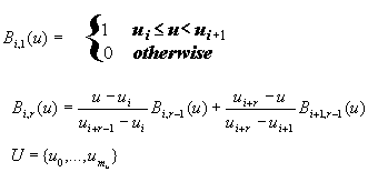 |
U is the knot vector containing a non-decreasing
sequence of real numbers.
mL is the last knot
vector in for the respective parameter.
4.16.3 Tessellation
By stepping through the u and v domains and evaluating the equation for points on the surface, a grid of sample points can be produced. Triangle strips can be generated by stepping through the u domain at two fixed v values.
The normals are computed by taking the cross product of the surface derivatives:
and normalizing the resulting vector.
This evaluation scheme is referred to in the literature as uniform tessellation. For a fixed tessellation, it is possible to precompute all the necessary basis functions Bi (u) and Bj(v). In addition, some properties of NURBS can be exploited. The control points are invariant to transformations. Thus, the small number of control points can be transformed instead of the huge number of output vertices. Furthermore, the convex hull property of NURBS states that the surface or curve lies completely within the convex hull formed by its control polygon. Hence, the control polygon can be used as bounding box for culling. It is also known that by repeatedly performing subdividision via knot insertion [Far96] the control polygon converges quadratically to the surface [Dahmen86]. By exploiting this fact, very tight bounding hulls can be computed.
As a drawback of a fixed step size the surfaces can be oversampled or undersampled: a flat surface may be broken up into a very fine mesh, or a surface of high curvature may be represented by a coarse mesh. This problem is addressed in the adaptive subdivision scheme as described in [Pet94]. Adaptive tessellation approximates the surface more accurately, especially in cases of highly varying curvature, but is more CPU-intensive. In this standard, a uniform tessellation is used due to its lesser computational requirements. If the NURBS surface is parameterized appropriately, the placement of the knot lines reflects the surface properties well. In areas of dense knot lines, the surface will be more complex than in areas with sparse knotlines. Hence, a tessellation formed by dividing knot intervals into a fixed number of subintervals will sample the surface accurately.
There is considerable literature on step size computation for uniform tessellation such as [RHD89], [FMM86], [AES91], [KML96]. There are two categories of algorithms, the size criterion and the deviation criterion. The size criterion determines the bound based on the size of the resulting triangles in screen space. Applying this step size to uniform tessellation still means that smooth areas are oversampled because the step size is related to the maximum curvature. The deviation criterion computes a bound on the maximum deviation of the tessellated surface from the NURBS surface. The deviation criterion produces good results but is computationally expensive.
4.16.4 Trimmed NURBS
To describe arbitrary shapes, trimmed NURBS patches are introduced. Here, trimming loops, which are specified in parameter space of a surface, mark invalid regions of the NURBS patch domain (see Figure 4.6). The area within the trimming loop is considered the invalid region. Especially in the CAD domain, trimmed NURBS are used to design objects with fluid shapes like ship hulls and aircraft or car bodies. Also, in solid modelling, patches containing holes are represented in trimmed form.�
Trimming loops consist of one or more trimming curves, which are 2D NURBS curves or piecewise linear curves, lying in the parameter space of the surface and forming a closed loop. An area inside a loop is considered invalid if the loop is defined in a clockwise direction. If the loop is defined in a counterclockwise direction, the area inside is retained and outside is considered invalid. The outermost contour shall be defined in a counterclockwise direction. Clockwise is determined as follows:
-
Take the cross-product of u and v in parameter space. This generates a normal to the parameter space plane.
-
While looking in the negative direction of the normal vector towards the parameter space plane, clockwise is defined to be the direction scribed by moving from the positive v axis to towards the positive u axis.
The contours shall not be self-intersecting or intersect other contours. They may however be nested. When nested, each trimming contour nesting level shall alternate clockwise direction. Multiple non-intersecting tirmming contours may exist at any nesting level. Degenerate forms such as self-intersecting trimming loops and intersecting loops need special attention from the application so that the degenerate contours are split into non intersecting loops.
|
Figure 4.6: Trimmed NURBS patch with lines showing a possible tessellation |
4.16.5 Using NURBS for animation
NURBS can be simply animated by alteration of single control vertices. Thereby, the NURBS surface will always keep its smoothness. With the order of the surface, the impact of the control vertex animation on adjacent control points and the range of the animation can be changed.
NURBS are also applicable for the animation of values using smooth curves expressed in NURBS format. An adaption of the VRML PositionInterpolator node to a NURBS description leads to the NurbsPositionInterpolator.
Extending the concept NurbsCurve (one Parameter), NurbsSurface (two parameters) to the parametric dimension 3 results in a NURBS volume. Given a (u,v,w) parameter as input, a 3D (x,y,z) output can be computed. The CoordinateDeformer defines a volume and applies a space warp to this volume. Any given conventional Coordinate node can be deformed by this node. This concept can also be found in animation programs in the form of a Free Form Deformation (FFD).
�
Pages 68 through 131
6 Node reference
Insert alphabetically the following new node definitions adding appropriate subclause numbers, update the Table of contents (Table 6.1),renumber the figures and tables, and update all applicable hyperlinks:
"![]()
 6.xx� Contour2D
Contour2D {
eventIn����� MFNode� addChildren
eventIn����� MFNode� removeChildren
exposedField MFNode �children�� []
}
�
The Contour2D node groups a set of curve segments to a composite contour. The children shall form a closed loop with the first point of the first child repeated as the last point of the last child and the last point of a segment repeated as the first point of the consecutive one. The segments shall be defined either by NurbsCurve2D or Polyline2D nodes and shall be enumerated in the child field in consecutive order according to the topology of the contour.�
Nested Contour2D nodes alternately specify invalid and valid regions depending on the clockwiseness of the contours. Additionally, each Contour2D may contain multiple, non-intersecting Contour2D nodes. This allows specification of multiple invalid or valid regions within a single outerlying valid or invalid region. See 4.16.4 Trimmed NURBS for a description of how clockwiseness is computed.
![]()
6.xx�
CoordinateDeformer
CoordinateDeformer {
eventIn����� MFNode�� addChildren
eventIn �����MFNode�� removeChildren
exposedField MFNode children��������� []
exposedField MFVec3f controlPoint [] # (-∞,∞)
exposedField MFNode � inputCoord������� []
exposedField MFNode � inputTransform��� []
exposedField MFNode � outputCoord������ []
exposedField MFFloat weight [] # (-∞,∞)
field������� SFVec3f �bboxCenter������� 0 0 0 # (-∞,∞)
field������� SFVec3f �bboxSize��������� -1 -1 -1 # (0,∞) or (-1,-1,-1)
field������� SFInt32� uDimension����� � 0���� ����� # [0,∞)
field������� MFFloat �uKnot���������� � []��� ����� # (-∞,∞)
field������� SFInt32� uOrder��������� � 2���� ����� # [2,∞)
field������� SFInt32� vDimension����� � 0���� ����� # [0,∞)
field������� MFFloat �vKnot���������� � [] # (-∞,∞)
field������� SFInt32� vOrder 2 # [2,∞)
field������� SFInt32� wDimension����� � 0���� ����� # [0,∞)
field������� MFFloat �wKnot [] # (-∞,∞)
field������� SFInt32� wOrder 2 # [2,∞)
}
CoordinateDeformer allows a free form deformation on a set of MFVec3f Coordinate nodes by using a NURBS volume. Conceptually, a set of input Coordinate nodes is placed into a non-uniform grid volume. If the grid control points are animated or deformed the output Coordinate nodes are updated accordingly.
The input to the deformer is a list of Coordinate nodes, where each Coordinate node defines a 3D parameter (u,v,w) for evaluation. The corresponding Cartesian output value is computed from the NURBS control grid. The children node contains a scene graph that typically consists of IndexedFaceSet nodes referring to a deformed Coordinate node in outputCoords.
The uDimension, vDimension, wDimension, controlPoint, weight, uKnot, vKnot, wKnot, uOrder, vOrder, and wOrder fields define the NURBS in three dimensions. The definition is similar to the NurbsSurface node.
The inputCoord field, if specified, shall contain a set of Coordinate nodes.
The outputCoord field, shall contain a set of Coordinate nodes. The number of nodes shall be equal to the number of nodes in inputCoord. The nodes themselves should be distinct from nodes in inputCoords.
The inputTransform field, if specified, shall contain a set of Transform nodes, the number of nodes shall be equal to the number of nodes in inputCoord.
By animating the controlPoint field, IndexedFaceSet nodes using a Coordinate node from outputCoords are deformed over time. Similarly, the point field in an input Coordinate node can be animated. By changing a Transform node in the inputTransform parameter, geometry can be moved through the deformation space (space warp).
CoordinateDeformer is a group node and shall be part of the transform hierarchy if evaluation is required. Points in the Coordinate node contained in outputCoord are recomputed and updated whenever the points of the inputCoord Coordinate are changed, any exposedField of the CoordinateDeformer itself is changed, or if any of the supplied inputTransform nodes are changed. Implementations may defer or even skip evaluation until the CoordinateDeformer node is displayed; i.e., if the node is not currently part of the traversed scene graph, or the node is not being rendered because the bounding box of the node (or the bounding box computed from the controlPoint list) falls outside the view frustum.
In some respects, CoordinateDeformer is a special version of a CoordinateInterpolator. The CoordinateDeformer is a group node in order to make the animation locatable in the scene graph at a certain 3D position. Normally, VRML interpolators do not define a bounding box and so are not culled from the scene. This behaviour may be achieved explicitly by routing the output of a VisibilitySensor to the controlling TimeSensor node.
Example:
DEF FFD CoordinateDeformer� {
������� controlPoint [ ... ]��������
������� inputCoord�� DEF inputCoord� Coordinate� { point [ ... ] }
������� outputCoord� DEF outputCoord Coordinate� { point [ ... ] }
������� children Shape {
��������������� geometry IndexedFaceSet {
����������������������� coord USE outputCoord
������������������ coordIndex [ ... ]
��������������� }
������� }
}
The following is additional code to animate the FFD node:
DEF Timer TimeSensor {}
DEF FFDGridInterpolator CoordinateInterpolator { ... }
ROUTE FFDGridInterpolator.value_changed TO FFD.set_controlPoint
ROUTE Timer.fraction_changed O FFDGridInterpolator.set_fraction
If a given input coordinate value (optionally transformed by the corresponding Transform node) exceeds the parametric range of one of the knot vectors, the corresponding output coordinate value will be left unchanged. This is useful to deform only a subset of the coordinates or to animate different parts of the coordinate node using different CoordinateDeformer nodes.
![]()
6.xx GeoCoordinate
GeoCoordinate {
 field   SFNode     geoOrigin     NULL
 field   MFString   geoSystem     ["GD","WE"]
 field   MFString   point         []
}
The GeoCoordinate node specifies a list of coordinates in a spatial reference frame. It is used in the coord field of vertex-based geometry nodes including IndexedFaceSet, IndexedLineSet, and PointSet. This is an optionally-implemented VRML node that constitutes part of the VRML support for geospatial applications, see 4.15, Geospatial application support.
The geoOrigin field is used to specify a local coordinate frame for extended precision as described in 4.15.5 Dealing with high-precision coordinates.
The geoSystem field is used to define the spatial reference frame and is described in 4.15.3, Encoding a spatial reference frame.
The point string array is used to contain the actual geospatial coordinates and should be provided in a format consistent with that specified for the particular geoSystem (see 4.15.4 Encoding geospatial coordinates). The geospatial coordinates are transparently transformed into a geocentric, curved-earth representation. For example, this would allow a geographer to create a VRML world where they specify all coordinates in terms of latitude, longitude, and elevation.
![]()
6.xx GeoElevationGrid
GeoElevationGrid {
 eventIn        MFFloat    set_height
 eventIn        SFFloat    set_yScale
 exposedField   SFNode     color              NULL
 exposedField   SFNode     normal             NULL
 exposedField   SFNode     texCoord           NULL
 field          SFBool     ccw                TRUE
 field          SFBool     colorPerVertex     TRUE
 field          SFFloat    creaseAngle        0             # [0,∞)
 field          SFNode     geoOrigin          NULL
 field          MFString   geoSystem          ["GD","WE"]
 field          SFString   geoGridOrigin      "0 0 0"
 field          MFFloat    height             []            # (-∞,∞)
 field          SFBool     normalPerVertex    TRUE
 field          SFBool     solid              TRUE
 field          SFInt32    xDimension         0             # [0,∞)
 field          SFString   xSpacing           "1.0"
 field          SFFloat    yScale             1.0           # (0,∞)
 field          SFInt32    zDimension         0             # [0,∞)
 field          SFString   zSpacing           "1.0"
}
The GeoElevationGrid node specifies a uniform grid of elevation values within some spatial reference frame. These are then transparently transformed into a geocentric, curved-earth representation. For example, this would allow a geographer to create a height field where all coordinates are specified in terms of latitude, longitude, and elevation.
The fields color, colorPerVertex, texCoord, normal, and normalPerVertex all have the same meaning as they do for a standard VRML ElevationGrid.
The ccw, solid, and creaseAngle fields are described in 4.6.3, Shapes and geometry.
The geoOrigin field is used to specify a local coordinate frame for extended precision as described in 4.15.5 Dealing with high-precision coordinates.
The geoSystem field is used to define the spatial reference frame and is described in 4.15.3, Encoding a spatial reference frame.
The geoGridOrigin field specifies the geospatial coordinate for the south-west corner (bottom-left) of the dataset. This value should be given in the format described in 4.15.4, Encoding geospatial coordinates.
The height array contains xDimension * zDimension floating point values that represent elevation above the ellipsoid or the geoid, as appropriate. These values are given in row-major order from west to east, south to north. When the geoSystem is GD, xSpacing refers to the number of degrees of longitude between adjacent height values and zSpacing refers to the number of degrees of latitude between vertical height values. When the geoSystem is UTM, xSpacing refers to the number of eastings (metres) between adjacent height values and zSpacing refers to the number of northings (metres) between vertical height values. (Hint: if xDimension = n and the grid spans d units horizontally, the xSpacing value should be set to d / (n-1) ). An eventIn called set_height is provided to allow the height array to be modified dynamically, for example, to support deformations or morphing of terrain surfaces.
The yScale value can be used to produce a vertical exaggeration of the data when it is displayed. By default, this value is 1.0 (no exaggeration). If this value is set to a value greater than 1.0, all heights will appear larger than they actually are. This can be useful for emphasizing elevation change, but the images produced will not represent the true elevation unless yScale is 1.0. An eventIn called set_yScale is provided to allow the vertical exaggeration factor to be altered dynamically.
![]()
6.xx GeoLocation
GeoLocation {
 exposedField  SFString   geoCoords           ""
 field         MFNode     children            []
 field         SFNode     geoOrigin           NULL
 field         MFString   geoSystem           ["GD","WE"]

}
The GeoLocation node provides the ability to georeference any standard VRML model. That is, to take an ordinary VRML model, contained within the children field of the node, and to specify its location on the surface of the planet. This node is a grouping node that can be thought of as a Transform node. However, the GeoLocation node specifies an absolute location, not a relative one, so content developers should not nest GeoLocation nodes within each other.
The geoOrigin field is used to specify a local coordinate frame for extended precision as described in 4.15.5 Dealing with high-precision coordinates.
The geoSystem field is used to define the spatial reference frame and is described in 4.15.3, Encoding a spatial reference frame.
The geometry of the nodes in children is to be specified in units of metres in VRML coordinates relative to the location specified by the geoCoords field. The geoCoords field should be given in the format described in 4.15.4, Encoding geospatial coordinates.
The set_geoCoords eventIn can be used to dynamically update the location of a model (for example, via the output of a GeoPositionInterpolator).
In addition to placing a VRML model at the correct location on the planet, the GeoLocation node will also adjust the model's orientation appropriately. The standard VRML97 coordinate system specifies that the +Y axis = up, +Z = out of the screen, and +X = towards the right. The GeoLocation node will set the orientation so that, for the location specified, the +Y axis is the up direction for that local area (the normal to the tangent plane on the ellipsoid), -Z points towards the north pole, and +X is east.
Note that the children field of GeoLocation is not an exposedField and therefore the nodes specified cannot be changed at run-time. In order to support dynamically changing geometry, a Group node can be added as the top-level node and then the contents of that Group node can be modified through its children exposedField.
![]()
6.xx GeoLOD
GeoLOD {
 field      SFString  center        ""
 field      MFString  child1Url    []
 field      MFString  child2Url    []
 field      MFString  child3Url    []
 field      MFString  child4Url    []
 field      SFNode    geoOrigin    NULL
 field      MFString  geoSystem    ["GD","WE"]
 field      SFFloat   range        10              # [0,∞)
 field      MFString  rootUrl      []
 field      MFNode    rootNode     []
 eventOut   MFNode    children
}
The GeoLOD node provides a terrain specialized form of the LOD node. It is a grouping node that specifies two different levels of detail for an object using a tree structure, where 0 to 4 children can be specified, and also efficiently manages the loading and unloading of these levels of detail.
The level of detail is switched depending upon whether the user is closer or further than range metres from the geospatial coordinate that is defined by the field center. The format of the center field is described in 4.15.4, Encoding geospatial coordinates.
The geoOrigin field is used to specify a local coordinate frame for extended precision as described in 4.15.5 Dealing with high-precision coordinates.
The geoSystem field is used to define the spatial reference frame and is described in 4.15.3, Encoding a spatial reference frame.
When the user is outside the specified range, only the geometry for rootUrl or rootNode are displayed. When the viewer enters the specified range, this geometry is replaced with the contents of the four children files defined by child1Url through child4Url. The four children files are loaded into memory only when the user is within the specified range. Similarly, these are unloaded from memory when the user leaves this range. Figure 6.9 illustrates this process. Note however that there is no requirement that the child URLs be arranged in the same order as in the figure, i.e. child1Url does not need to represent the bottom-left quadtree child. Note also that it is valid to specify less than 4 child URLs, in which case the GeoLOD should switch to the children nodes when all of the specified URLs have been loaded. This latter feature can support tree structures other than quadtrees, such as binary trees.
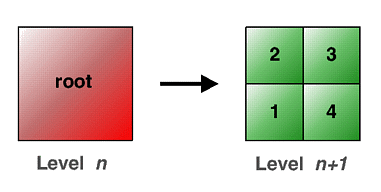
Figure 6.x -- Illustrating the GeoLOD level of detail transition
The rootUrl and rootNode fields provide two different ways to specify the geometry of the root tile. The rootNode field may be used to include the geometry for the root tile directly within the VRML file; whereas the rootUrl field specifies a URL for a file that contains the geometry. The result of specifying a value for both of these fields is undefined.
The children eventOut is used to expose the scene graph for the currently loaded set of nodes. The value returned is an MFNode with a single Switch node. This Switch node contains the root nodes in the first node of the choice field, and all the currently loaded children nodes in the second node of the choice field. The whichChoice field of the Switch node determines whether the root (0) or the children nodes (1) are being displayed. The GeoLOD node will generate a new children eventOut every time the scene graph is changed (e.g., whenever nodes are loaded or unloaded).
The GeoLOD node may be implemented with support for a cache of the most recent nodes that have been loaded. This cache should be global across all GeoLOD instances in a scene. This will improve performance when navigating large terrain models by avoiding excessive loading and unloading when a user makes small changes in viewpoint.
![]()
6.xx GeoMetadata
GeoMetadata {
 exposedField MFNode    data        []
 exposedField MFString  summary     []
 exposedField MFString  url         []
}
The GeoMetadata node aims to specify metadata describing any number of GeoVRML nodes. This can be thought of as similar to a WorldInfo node, but specifically for describing geospatial information.
There are a number of organizations that are already working on standards and representations for geospatial metadata, such as the FGDC, ISO TC211, CEN TC287, OpenGIS Consortium, and others. Rather than adopt any particular standard, the purpose of the GeoMetadata node is to provide links to any of these complete metadata descriptions, with the option to also supply a short, human-readable summary. It is not the purpose of the GeoMetadata node to introduce a new metadata standard.
The url field is used to specify a hypertext link to an external, complete metadata description. Multiple URL strings can be specified in order to provide alternative locations for the same metadata file. An optional hint can be provided in the summary field to specify the format of the metadata in the case where this cannot be deduced easily.
The summary string array contains a set of keyword/value pairs, with each keyword and its subsequent value contained in a separate string, i.e. there should always be an even (or zero) number of strings. This provides a simple, extensible mechanism to include metadata elements that are human-readable and easy to parse. The following list specifies a number of keywords and the format that should be used to describe their values. To support future additions to this list, if an unknown keyword is found, it (and its associated value) should be ignored.
Table 6.x -- GeoMetadata recommended keywords
|
Keyword |
Value |
|
title |
A name to succinctly identify the dataset to user. For example, "San Francisco, CA". |
|
description |
A brief textual description or summary of the content of the dataset. For example, "LANDSAT 7 satellite imagery taken over northern Scotland". |
|
coordinateSystem |
The spatial reference frame used to represent the data, e.g. GD, UTM, LCC, etc. The list of valid codes that can be used in this field are defined in Section 4.1 of E. [RI00]. In the case of UTM, the zone number should also be specified in the format "UTM Zx", where 1 <= x <= 60. For example, "UTM Z11". |
|
horizontalDatum |
The name of the geodetic datum. The list of valid codes that can be used in this field are defined in Section 4.3 of E. [RI00]. For example, "W84". |
|
verticalDatum |
The name of the vertical datum (geoid). The list of valid codes that can be used in this field are defined in Section 4.3 of E. [RI00]. For example, "W84". |
|
ellipsoid |
The name of the geodetic ellipsoid. The list of valid codes that can be used in this field are defined in Section 4.2 of E. [RI00]. For example, "WE". |
|
extent |
The bounding coordinates for the dataset given in spatial reference frame specified by the coordinateSystem keyword. These are provided in the order eastmost, southmost, westmost, northmost, followed by the minimum and maxiumum elevation for the dataset. An example for GD is: "-180.0 -90.0 180.0 90.0 0.0 2000.0". |
|
resolution |
The resolution, or ground sample distance, given in units of metres. For example, "30". |
|
originator |
A string defining the originator of the data, for example the author, agency, organization, publisher, etc. For example, "Martin Reddy, SRI International, Menlo Park, CA 94025" |
|
copyright |
Any appropriate copyright declaration that pertains to the data. For example, "(c) Copyright 2000, SRI International. All rights reserved. Freely distributable." |
|
date |
A single date/time, or a date/time range, defining the valid time period that the data pertains to. Dates are specified in the format "YYYY MM DD [HH:MM]". Years in the current time period should be specified using four digits, e.g. "1999" or "2001". Years can have other than 4 digits and can be negative. A date range is specified by supplying two values separated by a "-" character. An optional time can be supplied should this level of accuracy be required. Times are to be specified in 24-hour format with respect to GMT. For example, "1999 01 01 00:00 - 1999 12 31 23:59". |
|
metadataFormat |
A string that specifies the format of the external metadata description pointed to by url field of the GeoMetadata node. For example, "FGDC", "ISO TC211", "CEN TC287", "OGC", etc. |
|
dataUrl |
A hypertext link to the source data used to create the VRML node(s) these metadata pertain to. Multiple dataUrl keyword/value pairs can be specified in order to provide alternative locations for the same source file. For example, "http://www.foo.bar/data/sf1". |
|
dataFormat |
A free-text string that describes the format of the source data used to create the VRML node(s) that these metadata pertain to. This refers to the source data pointed to by the dataUrl keyword (if present). For example, "USGS 7.5-min DEM". |
The data field is used to list all of the nodes that implement the data described in the GeoMetadata node. For example, if the GeoMetadata node is describing a height field grid, the appropriate GeoElevationGrid node could be included inside the data field. The nodes in the data field are not rendered, so DEF/USE may be employed to first describe them and then to use them in the scene graph This approach associates multiple data nodes with a single GeoMetadata node, specifies multiple GeoMetadata nodes within a single scene, and provides a mechanism to easily locate all of the data that pertain to any particular metadata entry. If the data field is not specified, it is assumed that the GeoMetadata node pertains to the entire scene.
![]()
6.xx GeoOrigin
GeoOrigin {
 exposedField   MFString   geoSystem     ["GD","WE"]
 exposedField   SFString   geoCoords     ""
 field          SFBool     rotateYUp     FALSE
}
The GeoOrigin node defines an absolute geospatial location and an implicit local coordinate frame against which geometry is referenced. This node is used to translate from geospatial coordinates into a local Cartesian coordinate system which can be managed by the VRML browser.
The geoSystem field is used to define the spatial reference frame and is described in 4.15.3, Encoding a spatial reference frame.
The geoCoords field is used to specify the origin of the local coordinate frame and should be provided in a format consistent with that specified for the particular geoSystem (see 4.15.4, Encoding geospatial coordinates).
The rotateYUp field is used to specify whether all coordinates of any nodes that use this GeoOrigin should be rotated such that the up direction is aligned with the VRML Y axis. The default behaviour is to not perform this operation, which means that the local up direction will depend upon the location of the GeoOrigin with respect to the planet surface. The principal reason for performing the rotation is to ensure that standard VRML navigation modes such as FLY and WALK, which assume that +Y is up, will function correctly. Note that specifying rotateYUp to be TRUE may incur an extra computational overhead in order to perform the rotation for each point.
Since multiple local coordinate systems cannot be defined in a single scene, it is recommended that only one GeoOrigin node be defined within a single VRML world.� Then all subsequent geoOrigin fields can USE this GeoOrigin node.
![]()
6.xx GeoPositionInterpolator
GeoPositionInterpolator {
 eventIn       SFFloat   set_fraction                      # (-∞,∞)
 field         SFNode    geoOrigin           NULL
 field         MFString  geoSystem           ["GD","WE"]
 field         MFFloat   key                 []            # (-∞,∞)
 field         MFString  keyValue            []
 eventOut      SFString  geovalue_changed
 eventOut      SFVec3f   value_changed
}
The GeoPositionInterpolator node provides an interpolator capability where keyValues are specified in geospatial coordinates and the interpolation is performed within the specified spatial reference frame.
The geoOrigin field is used to specify a local coordinate frame for extended precision as described in 4.15.5 Dealing with high-precision coordinates.
The geoSystem field is used to define the spatial reference frame and is described in 4.15.3, Encoding a spatial reference frame.
The fields key, set_fraction, and value_changed have the same meaning as in the base VRML PositionInterpolator.
The keyValue string array is used to contain the actual coordinates and should be provided in a format consistent with that specified for the particular geoSystem. Each individual geospatial coordinate shall be provided in its own string within the array, e.g. [ "x1 y1 z1", "x2 y2 z2" ].
The geovalue_changed eventOut outputs the string defining the interpolated coordinate in the spatial reference frame specified by geoSystem. This can be passed to other GeoVRML nodes that support an eventIn of this form, e.g. GeoViewpoint and GeoLocation.
![]()
6.xx GeoTouchSensor
GeoTouchSensor {
 exposedField  SFBool    enabled                TRUE
 field         SFNode    geoOrigin              NULL
 field         MFString  geoSystem              ["GD","WE"]
 eventOut      SFVec3f   hitNormal_changed
 eventOut      SFVec3f   hitPoint_changed
 eventOut      SFVec2f   hitTexCoord_changed
 eventOut      SFString  hitGeoCoord_changed
 eventOut      SFBool    isActive
 eventOut      SFBool    isOver
 eventOut      SFTime    touchTime
}
A GeoTouchSensor node tracks the location and state of a pointing device and detects when the user points at geometry contained by the GeoTouchSensor's parent group. This node provides the same functionality as a TouchSensor but also provides the ability to return the geospatial coordinate under the pointing device. This is an optionally-implemented VRML node that constitutes part of the VRML support for geospatial applications, see 4.15, Geospatial application support.
A GeoTouchSensor can be enabled or disabled by sending an event of value TRUE or FALSE to the enabled field. A disabled GeoTouchSensor does not track user input or send events.
The geoOrigin field is used to specify a local coordinate frame for extended precision as described in 4.15.5 Dealing with high-precision coordinates.
The geoSystem field is used to define the spatial reference frame and is described in 4.15.3, Encoding a spatial reference frame.
The eventOuts hitNormal_changed, hitPoint_changed, hitTexCoord_changed, isActive, isOver, and touchTime all have the same meaning as in the base VRML TouchSensor node.
The hitGeoCoord_changed eventOut is generated while the pointing device is pointing towards the GeoTouchSensor's geometry, i.e. when isOver is TRUE. It is a string containing the geospatial coordinate for the point of intersection between the pointing device's location and the underlying geometry. The value of the geoSystem string defines the spatial reference frame that the geospatial coordinate is output using. For example, given the default geoSystem value of "GD", the string will be in the format "<latitude> <longitude> <elevation>" (see 4.15.4, Encoding geospatial coordinates).
![]()
6.xx GeoViewpoint
GeoViewpoint {
 eventIn        SFBool       set_bind
 eventIn        SFString     set_orientation
 eventIn        SFString     set_position
 exposedField   SFFloat      fieldOfView       0.785398       # (0,∞)
 exposedField   SFBool       headlight         TRUE
 exposedField   SFBool       jump              TRUE
 exposedField   MFString     navType           ["EXAMINE","ANY"]
 field          SFString     description       ""
 field          SFNode       geoOrigin         NULL
 field          MFString     geoSystem         ["GD","WE"]
 field          SFRotation   orientation       0 0 1 0        # [-1,1],(-∞,∞)
 field          SFString     position          "0 0 100000"
 field          SFFloat      speedFactor       1.0            # [0,∞)
 eventOut       SFTime       bindTime
 eventOut       SFBool       isBound
}
The GeoViewpoint node allows the specification of a viewpoint in terms of a geospatial coordinate.
This node can be used wherever a Viewpoint node can be used and also can combine GeoViewpoint and Viewpoint nodes in the same scene. The fieldOfView, jump, description, set_bind, bindTime, and isBound fields and events have the same behaviour as the standard Viewpoint node. Note that when a GeoViewpoint node is bound, it overrides the currently bound Viewpoint and NavigationInfo nodes in the scene.
The geoOrigin field is used to specify a local coordinate frame for extended precision as described in 4.15.5 Dealing with high-precision coordinates.
The geoSystem field is used to define the spatial reference frame and is described in 4.15.3, Encoding a spatial reference frame.
The position string is used to define the actual coordinate that locates the viewpoint. It should be provided in a format consistent with that specified for the particular geoSystem (see 4.15.4, Encoding geospatial coordinates). There is also a set_position eventIn which can be routed from the geovalue_changed eventOut of a GeoPositionInterpolator node in order to animate the position of the GeoViewpoint.
The orientation string defines a relative orientation from the local orientation frame that is defined by the position field. By default, the orientation of the viewpoint will always be aligned such that the +Y axis is the up vector for the local area (the normal to the tangent plane on the ellipsoid), -Z points towards the north pole, and +X is east. Therefore, if a GeoViewpoint that always looks straight down is to be created, no matter where on the planet the viewer may be looking, an orientation value of [ 1 0 0 -1.57 ] should be specifed. The set_orientation eventIn can be wired to the value_changed eventOut of a standard OrientationInterpolator in order to animate the orientation of the GeoViewpoint.
The navType field is used to specify the navigation type that is to be bound when this GeoViewpoint node is bound. The acceptable values for this field are the same as those for the type field of the NavigationInfo field node, e.g. "EXAMINE", "WALK", "FLY", or "ANY".
The headlight field is used to specify whether the browser shall turn on a headlight when this viewpoint is bound. A headlight is a directional light that always points in the direction that the user is looking.
The GeoViewpoint node may be implemented as if there is an embedded NavigationInfo node that is bound and unbound with the GeoViewpoint node. As such, a VRML browser shall internally set the speed, avatarSize, and visibilityLimit fields of such a NavigationInfo node to an appropriate value for the viewpoint's elevation. The VRML browser shall also continually update the speed field as the user moves in order to support elevation scaled velocity (see 4.15.6, Geospatial navigation issues). It is recommended that the speed of user interaction be defined as ( elev / 10.0 ) m/s, where elev is the elevation of the viewer above the WGS84 ellipsoid in units of metres. It is also recommended that the same scale factor be applied to the avatarSize vector and visibilityLimit value so that both the near and far clipping planes are updated.
The speedFactor field of the GeoViewpoint node is used as a multiplier to the elevation-based velocity that the node sets internally, i.e. this is a relative value and not an absolute speed as in the case for the NavigationInfo field of the same name.
![]()
6.xx InlineLoadControl
InlineLoadControl {
 exposedField SFBool    load           TRUE
 exposedField MFString  url            []
 field        SFVec3f   bboxCenter     0 0 0         # (-∞,∞)
 field        SFVec3f   bboxSize       -1 -1 -1      # [0,∞) or (-1,-1,-1)
 eventOut     MFNode    children
}
The InlineLoadControl node is a grouping node that reads its children data from a location in the World Wide Web. When its children are read and displayed is defined by the value of the load field.
If the load field is set to TRUE (the default value), the VRML world specified by the url field is loaded immediately. If the load field is set to FALSE, no action is taken. This node provides improved scalability over the Inline node which does not define when the world to which the url field is pointed should be loaded.
If the load field is set to FALSE, it is possible to explicitly load the URL at a later point by sending a TRUE event to the set_load eventIn of the node (e.g., via a ProximitySensor or other sensor). Similarly, if a FALSE event is sent to set_load, any currently loaded world will be unloaded from the scene graph.
The set_url eventIn can be used to change the world that is inlined by the InlineLoadControl node. If this value is set while a world is already loaded, that world will be unloaded and the new world that is pointed to by the new URL will be inlined.
The children eventOut is used to expose the scene graph hierarchy for the loaded VRML world. This is useful if the new nodes are to be inspected using an external interface or script. This functionality is not available using the base VRML Inline node.
The user is able to specify a bounding box for the InlineLoadControl node using the bboxCenter and bboxSize fields. This is a hint to the browser and could be used for optimization purposes such as culling.
![]()
6.xx�
NurbsCurve
NurbsCurve{
exposedField MFVec3f controlPoint []��� # (-∞,∞)
exposedField MFFloat weight������ []��� # (0,∞)
exposedField SFInt32 tessellation 0���� # (-∞,∞)
field������� MFFloat knot�������� []��� #
(-∞,∞)
field������� SFInt32 order������� 3���� # [2,∞)
}
The NurbsCurve node is a geometry node defining a parametric curve.�
Order defines the order of curve. From a mathematical point of view, the curve is defined by a polynomial of the degree order-1. The value of Order shall be greater than or equal to 2. An implementation may limit Order to a certain number. The most common orders are 3 (quadratic polynomial) and 4 (cubic polynomial), which are sufficient to achieve the desired curvature in most cases. The number of control points shall be at least equal to the order of the curve. The order defines the number of adjacent control points that influence a given control point.�
The control points define a piecewise linear curve, where the points do not have a uniform spacing. Depending on the weight value and the order, this piecewise linear curve is approximated by the resulting parametric curve. The number of control points shall be equal to or greater than the order. The control points are all defined as 3D vertices in the x, y, z domain. A closed B-Spline curve can be specified by repeating the limiting control points and by specifying a periodic knot vector.
A weight value that shall be greater than zero is assigned to each controlPoint. The ordering of the values is equivalent to the ordering of the control point values. If the weight of a control point increased above 1, the point is more closely approximated by the curve. However the curve is not changed if all weights are multiplied by a common factor. The number of values shall be identical to the number of control points. If the length of the weight vector is 0, the default weight 1.0 is assumed for each control point.
As a result of the lack of a 4D Coordinate field type in VRML, the control points and the corresponding weight values are held in separate fields. This separation also allows independent animation of the controlPoint fields using a CoordinateInterpolator node.
knots defines the knot vector. The number of knots shall be equal to the number of control points plus the order of the curve. The order shall be non-decreasing. By setting successive knot values equal, the degree of continuity is decreased, which implies that the curve has corners. In general, the curve is of continuity Ck-1-m at a knot point, where k is the order and m is the number of consecutive knots being equal. If k is the order of the curve, k consecutive knots at the end or the beginning of the vector cause the curve to interpolate the last or the first control point respectively. Within the knot vector there may not be more than k-1 consecutive knots of equal value. If the length of a knot vector is 0, a default uniform knot vector is computed.
The tessellation field gives a hint to the curve tessellator by setting an absolute number of subdivision steps. These values shall be greater than or equal to the Order field. A value of 0 indicates that the browser choose a suitable tessellation. Interpretation of values below 0 is implementation dependent.
For an implementation subdividing the surface into an equal number of subdivision steps, tessellation values are interpreted in the following way:
a.������ if a
tessellation value is greater than 0, the number of tessellation
points is
tessellation+1;
b.������ if a
tessellation value is smaller than 0, the number of tessellation
points is
(-tessellation × (number of control
points)+1;
c.������ if a
tessellation value is 0, the number of tessellation points is
(2 × (number of control
points)+1.
For implementations doing tessellations based on chord length, tessellation values� less than zero are interpreted as the maximum chord length deviation in pixels. Implementations doing fully automatic tessellation may ignore the tessellation hint parameters.
�
![]()
6.xx�
NurbsCurve2D
NurbsCurve2D � {
exposedField MFVec2f controlPoint��� []��� # (-∞,∞)
exposedField SFInt32 tessellation��� 0 # (-∞,∞)
exposedField MFFloat weight��������� []��� # (0,∞)
field������� MFFloat knot����������� []��� # (-∞,∞)
field������� SFInt32 order���������� 3���� # [2,∞)
}
�
The NurbsCurve2D node defines a trimming segment that is part of a trimming contour in the u, v domain of the surface. The control points are all defined as 2D vertices in u, v domain. NurbsCurve2D are used as children to the Contour2D group.
In other respects, the NurbsCurve2D has the same functionality as defined for the NurbsCurve node.
![]()
6.xx�
NurbsGroup
NurbsGroup {
eventIn����� MFNode� addChildren
eventIn����� MFNode� removeChildren
exposedField MFNode �children�� �������� []
exposedField SFFloat tessellationScale 1.0����� # (0,∞)
field������� SFVec3f bboxCenter 0 0 0��� # (-∞,∞)
field������� SFVec3f bboxSize�� �������� -1 -1 -1 # (0,∞) or (-1,-1,-1)
}
�
The NurbsGroup node groups a set of NurbsSurface nodes to a common group. This provides a hint to the browser to treat the set of NurbsSurface nodes appearing in a Shape node in children as a unit during tessellation to enforce tessellation continuity along borders. The tessellationScale parameter scales the tessellation values in lower-level NurbsCurve and NurbsSurface nodes. If a set of NurbsSurfaces uses a matching set of control points along the borders, this results in a common tessellation stepping.
![]()
6.xx�
NurbsPositionInterpolator
NurbsPositionInterpolator {
� eventIn����� SFFloat� set_fraction��� ������� # (-∞,∞)�����
� exposedField SFInt32� dimension������� 0 # (-∞,∞)
� exposedField MFVec3f� keyValue�������� [] # (-∞,∞)
� exposedField MFFloat� keyWeight������� [] # (-∞,∞)
� exposedField MFFloat� knot������������ [] # (-∞,∞)
� exposedField SFInt32� order����������� 4 # [2,∞)
� eventOut�� � SFVec3f� value_changed
}
NurbsPositionInterpolator describes a 3D NURBS Curve using dimension, keyValue, keyWeight, knot, and order as described for the NurbsCurve node.�
The fields set_fraction and value_changed have the same meaning as in the base VRML PositionInterpolator.
Sending a set_fraction input computes a 3D position on the curve, which is sent by value_changed. The set_fraction value is used as the input value for the tessellation function. Thereby, the knot corresponds to the key field of a conventional interpolator node; i.e., if the set_fraction value is within [0;1] and the knot vector within [0;2], only half of the curve is computed.
![]()
6.xx�
NurbsSurface
NurbsSurface� {
exposedField MFVec3f controlPoint� � [] # (∞,∞)
exposedField SFNode� texCoord���� �� []
exposedField SFInt32 uTessellation 0 # (-∞,∞)
exposedField SFInt32 vTessellation 0��� � # (-∞,∞)
exposedField MFFloat weight������ �� [] # (0,∞)
field������� SFBool� ccw��������� �� TRUE
field������� SFBool� solid������� �� TRUE
field������� SFInt32 uDimension 0 # [0,∞)
field������� MFFloat uKnot [] # (-∞,∞)
field������� SFInt32 uOrder 3 # [2,∞)�
field������� SFInt32 vDimension 0 # [0,∞)
field������� MFFloat vKnot [] # (-∞,∞)
field������� SFInt32 vOrder 3 # [2,∞)
}
�
The NurbsSurface node is a geometry node defining a parametric surface.
uDimension and vDimension define the number of control points in the u and v dimensions. uOrder and vOrder define the order of surface. From a mathematical point of view, the surface is defined by polynomials of the degree order-1. The value of uOrder and vOrder shall be greater than or equal to 2. An implementation may limit uOrder and vOrder to a certain number. The most common orders are 3 (quadratic polynomial) and 4 (cubic polynomial), which are sufficient to achieve the desired curvature in most cases. The number of control points shall be at least equal to the order of the curve. The order defines the number of adjacent control points that influence a given control point.
controlPoint defines a set of control points of dimension:�� uDimension × vDimension.� This set of points defines a mesh similar to the grid of an ElevationGrid, where the points do not have a uniform spacing. Depending on the weight values and the order, this hull is approximated by the resulting surface. The number of uDimension points define a polyline in u-direction followed by further u-polylines with the v-parameter in ascending order. The number of control points shall be equal to or greater than the order. The control points are all defined as 3D vertices in the x, y, z domain. A closed B-Spline surface can be specified by repeating the limiting control points and by specifying a periodic knot vector.
The control vertex corresponding to the control point P[i, j] on the control grid is:
P[i,j].x = controlPoints[i + ( j × uDimension)].x
P[i,j].y = controlPoints[i + ( j × uDimension)].y
P[i,j].z = controlPoints[i + ( j × uDimension)].z
P[i,j].w = weight[ i + (j × uDimension)]
where 0 <= i < uDimension and 0 <= j < vDimension.
A weight value that shall be greater than zero is assigned to each controlPoint. The ordering of the values is equivalent to the ordering of the control point values. If the weight of a control point increased above 1 the point is more closely approximated by the surface. However the surface is not changed if all weights are multiplied by a common factor. The number of values shall be identical to the number of control points. If the length of the weight vector is 0, the default weight 1.0 is assumed for each control point.
As a result of the lack of a 4D Coordinate field type in VRML, the control points and the corresponding weight values are held in separate fields. This separation also allows independent animation of the controlPoint fields using a CoordinateInterpolator node.
uKnots and vKnots define the knot vector. The number of knots shall be equal to the number of control points plus the order of the curve. The order shall be non-decreasing. By setting successive knot values equal, the degree of continuity is decreased, which implies that the surface gets edges. In general, the curve or surface is of continuity Ck-1-m at a knot point, where k is the order and m is the number of consecutive knots being equal. If k is the order of the curve, k consecutive knots at the end or the beginning of the vector cause the curve to interpolate the last or the first control point respectively. Within the knot vector there may not be more than k-1 consecutive knots of equal value. If the length of a knot vector is 0, a default uniform knot vector is computed.
The uTessellation and vTessellation fields give hints to the surface tessellator by setting an absolute number of subdivision steps. These values shall be greater than or equal to the uOrder and vOrder fields, respectively. A value of 0 lets the browser choose a suitable tessellation. Interpretation of values below 0 is implementation dependent.
For an implementation subdividing the surface into an equal number of subdivision steps, tessellation values are interpreted in the following way:
a.������ if a
tessellation value is greater than 0, the number of tessellation
points is
tessellation+1;
b.������ if a
tessellation value is smaller than 0, the number of tessellation
points is
(-tessellation ×
(u/v)dimension)+1;
c.������ if a
tessellation value is 0, the number of tessellation points is
(2 × (u/v)dimension)+1.
For implementations doing tessellations based on chord length, tessellation values less than zero are interpreted as the maximum chord length deviation in pixels. Implementations doing fully automatic tessellation may ignore the tessellation hint parameters.
texCoord may provide additional information on how to generate texture coordinates. There are three possible values:� a NULL node, a TextureCoordinate node, or a NurbsTextureSurface node. For the default case of a NULL node, texture coordinates in the unit square are generated automatically from the parametric subdivision. If either a TextureCoordinate node or a NurbsTextureSurface node is provided, a texture coordinate is computed given a (u, v) parameter of the NurbsSurface.
Subclause 4.6.3, Shapes and geometry, provides a description of the ccw and solid fields.
![]()
6.xx�
NurbsTextureSurface
NurbsTextureSurface {
exposedField MFVec2f controlPoint []��� # (-∞,∞)
exposedField MFFloat weight []��� # (0,∞)
field������� SFInt32 uDimension 0���� # [0,∞)�
field������� MFFloat uKnot []��� # (-∞,∞)
field������� SFInt32 uOrder 3���� # [2,∞)
field������� SFInt32 vDimension 0���� # [0,∞)
field������� MFFloat vKnot []��� # (-∞,∞)
field������� SFInt32
vOrder 3���� #
[2,∞)
}
The NurbsTextureSurface node is a NURBS surface existing in the parametric domain of its surface host specifying the mapping of the texture onto the surface.�
The parameters are as specified for the NurbsSurface node with the exception that the control points are specified in (u, v) coordinates.
The tessellation process generates 2D texture coordinates. If the NurbsTextureSurface is undefined, texture coordinates are computed by the client on the basis of parametric step size. Conventional vertex parameters do not apply on NURBS because triangles are only available after polygonization, but the conventional texture transform may be used.
NurbsTextureSurface nodes are accessed through the texCoord field of the NurbsSurface node. A NurbsTextureSurface node separately encountered is ignored.
![]()
6.xx�
Polyline2D
Polyline2D � {
exposedField MFVec2f� point��� []
}
�
The Polyline2D node defines a piecewise linear curve segment as a part of a trimming contour in the u-v domain of a surface.�
point specifies the end points of the piecewise linear curve.
Polyline2D are used as children to the Contour2D group.
![]()
6.xx�
TrimmedSurface
TrimmedSurface {
eventIn����� MFNode addTrimmingContour
eventIn����� MFNode removeTrimmingContour
exposedField MFNode trimmingContour�� ����� []
�exposedField SFNode surface��������� ������ NULL�
}
The TrimmedSurface node defines a NURBS surface that is trimmed by a set of trimming loops. The outermost trimming loop shall be defined in a counterclockwise direction.
The surface field shall contain a NurbsSurface node that is to be trimmed.�
The trimmingContour field, if specified, shall contain a set of Contour2D nodes.�Trimming loops shall be processed as described for the Contour2D node."
Pages 96 through 98
6.23 IndexedFaceSet
Replace all occurrences of "Coordinate node" with "Coordinate or GeoCoordinate node".
Page 109
6.36� PointSet
Replace the 2nd sentence with the following text and update the hyperlinks:
"The coord field specifies a Coordinate or GeoCoordinate node (or instance of such a node)."
Page 110
Replace the last sentence of the 3rd paragraph with the following text:
"The results are undefined if the number of values in the Color node is less than the number of values specified in the Coordinate or GeoCoordinate node."
6.40� Script
The following text replaces the first sentence of the third paragraph:
"Browsers are required to support the ECMAScript language and may support scripting in any other language."
6.53� Viewpoint
Replace the phrase which starts the 3rd sentence of item d. with the following text and update the hyperlinks:
"Nodes contained within Inline or InlineLoadControl nodes,"
7 Conformance
7.3.3� VRML requirements for conforming to the base profile
Page 138
The following text replaces the last sentence in the third column of the Script row of Table 7.1:
"Support for ECMAScript scripting required."
Append the following text as new subclauses:
"7.4� Geospatial support
This specification includes a number of optional nodes for supporting geospatial and geospatial applications. These nodes are listed in 4.15.1 Introduction and defined in the appropriate clauses of 6 Node reference. A VRML browser is not required to implement these nodes in order to conform to this specification. However, if a VRML browser does implement these nodes, it shall conform to the requirements enumerated in Table 7.2. The columns in Table 7.2 have the same meaning as defined in 7.3.3 VRML requirements for conforming to the base profile.
To increase interoperability, it is recommended that relevant EXTERNPROTO definitions be provided as shown in Annex G and as described in F.3 Browser extensions if any of these optional nodes are used in a VRML world.
�
Table 7.2 -- Specifications for VRML browsers offering geospatialsupport |
||
|
Item |
VRML File Limit |
Minimum Browser Support |
|
All groups |
500 children. |
500 children. Ignore bboxCenter and bboxSize. |
|
All geospatial nodes |
n/a |
All spatial reference frames, geoids, and ellipsoids. |
|
GeoCoordinate |
30,000 utf8 octets per string, 10 strings |
30,000 utf8 octets per string, 10 strings |
|
GeoElevationGrid |
16,000 heights. |
16,000 heights. |
|
InlineLoadControl |
No restrictions. |
Full support except as for all groups. url references VRML files conforming to the base profile. |
|
GeoLocation |
Restrictions as for all groups. |
Full support except as for all groups. |
|
GeoLOD |
Restrictions as for all groups. |
Implementation may disregard range distance. |
|
GeoMetadata |
No restrictions. |
Ignored. |
|
GeoOrigin |
One unique set of values allowed. |
Ignore rotateYUp. |
|
GeoPositionInterpolator |
1000 key-value pairs. |
1000 key-value pairs. |
|
GeoTouchSensor |
No restrictions. |
Full support. |
|
GeoViewpoint |
No restrictions. |
Ignore fieldOfView. Ignore description. Evaluate elevation-scaled navigation speed on node initialization only. |
7.5� NURBS support
This specification includes a number of optional nodes for supporting NURBS representation. These nodes are listed in 4.16.1 Introduction and defined in the appropriate clauses of 6 Node reference. A VRML browser is not required to implement these nodes in order to conform to this specification. However, if a VRML browser does implement these nodes, it shall conform to the requirements enumerated in Table 7.3. The columns in Table 7.3 have the same meaning as defined in 7.3.3 VRML requirements for conforming to the base profile.
To increase interoperability, it is recommended that relevant EXTERNPROTO definitions be provided as shown in Annex G and as described in F.3 Browser extensions if any of these optional nodes are used in a VRML world.
�
Table 7.3 -- Specifications for VRML browsers offering NURBS support |
||
|
Item |
VRML File Limit |
Minimum Browser Support |
|
All groups |
500 children. |
500 children. Ignore bboxCenter and bboxSize. |
|
Contour2D |
No restrictions. |
If used as trimmingContour in TrimmedSurface ignore, If used as geometry node draw contour as wireframe. |
|
CoordinateDeformer |
16,000 values per array. |
16,000 values per array,� uOrder, vOrder <= 8 |
|
NurbsCurve |
16,000 values per array. |
16,000 values per array , ignore tessellation,� order <= 8 |
|
NurbsCurve2D |
same as NurbsCurve. |
same as NurbsCurve. |
|
NurbsGroup |
Restrictions as for all groups. |
Full support except as for all groups, Ignore tessellationScale. |
|
NurbsPositionInterpolator |
16,000 values per array. |
16,000 values per array, order <= 8 |
|
� |
� |
� |
|
NurbsSurface |
16,000 values per array. |
16,000 values, Ignore uTessellation, vTessellation, uOrder, vOrder <= 8, Ignore TexCoord |
|
NurbsTextureSurface |
16,000 values per array. |
16,000 values,� uOrder, vOrder <= 8 |
|
Polyline2D |
No restrictions. |
Full support. |
|
TrimmedSurface |
No restrictions. |
Ignore trimmingContour. |
Page 148
B.1� Java platform scripting reference
In the 1st sentence, renumber the reference 6.40, Script and update the hyperlink.
Page 185
C.1� ECMAScript scripting reference
In the 1st sentence, renumber the reference 6.40, Script and update the hyperlink.
The following text replaces the last sentence of the first paragraph:
"Any access of ECMAScript from within VRML Script nodes shall conform with the requirements specified in this annex."
Page 185
C.3.1�
url field
The following text replaces the third paragraph:
"Browsers shall support the javascript: protocol as well as the other required protocols (see 7, Conformance and minimum support requirements)."
Page 232
D� Examples
Page 232
Insert the following additional subclauses:
D.x� Georeferencing VRML objects
This example displays a standard VRML cone at the latitude/longitude location of Lossiemouth, Scotland. The Cone is rotated through 180 degrees about the X axis to point straight down rather than up. The GeoElevationGrid node is used in order to provide a (coarse) underlying reference model of the Earth. The Cone is 500 km high and 200 km above the surface of the Earth so that it can be seen as shown in Figure D.x.
#VRML V2.0 utf8

EXTERNPROTO GeoLocation [
  exposedField SFString geoCoords
  field        MFNode   children
  field        SFNode   geoOrigin
  field        MFString geoSystem
] [ "urn:web3d:vrml97:node:GeoLocation"
    "file:///C:/Program%20Files/GeoVRML/1.1/protos/GeoLocation.wrl"
    "file:///C|/Program%20Files/GeoVRML/1.1/protos/GeoLocation.wrl"
    "http://www.geovrml.org/1.1/protos/GeoLocation.wrl" ]

EXTERNPROTO GeoElevationGrid [
  exposedField SFNode   color
  exposedField SFNode   normal
  exposedField SFNode   texCoord
  field        SFBool   ccw
  field        SFBool   colorPerVertex
  field        SFFloat  creaseAngle
  field        SFNode   geoOrigin
  field        MFString geoSystem
  field        SFString geoGridOrigin
  field        MFFloat  height
  field        SFBool   normalPerVertex
  field        SFBool   solid
  field        SFInt32  xDimension
  field        SFString xSpacing
  field        SFInt32  zDimension
  field        SFString zSpacing
] [ "urn:web3d:vrml97:node:GeoElevationGrid"
    "file:///C:/Program%20Files/GeoVRML/1.1/protos/GeoElevationGrid.wrl"
    "file:///C|/Program%20Files/GeoVRML/1.1/protos/GeoElevationGrid.wrl"
    "http://www.geovrml.org/1.1/protos/GeoElevationGrid.wrl" ]

EXTERNPROTO GeoViewpoint [
  eventIn      SFBool     set_bind
  eventIn      SFString   set_position
  eventIn      SFString   set_orientation
  exposedField SFFloat    fieldOfView
  exposedField SFBool     headlight
  exposedField SFBool     jump
  exposedField MFString   navType
  field        SFString   description
  field        SFNode     geoOrigin
  field        MFString   geoSystem
  field        SFRotation orientation
  field        SFString   position
  field        SFFloat    speed
  eventOut     SFTime     bindTime
  eventOut     SFBool     isBound
] [ "urn:web3d:vrml97:node:GeoViewpoint"
    "file:///C:/Program%20Files/GeoVRML/1.1/protos/GeoViewpoint.wrl"
    "file:///C|/Program%20Files/GeoVRML/1.1/protos/GeoViewpoint.wrl"
    "http://www.geovrml.org/1.1/protos/GeoViewpoint.wrl" ]

Group {
  children [

    Background { skyColor 1 1 1 }

    GeoViewpoint {
       geoSystem [ "GD" ]
       position "51.5122 -40.0 10000000"
       orientation 1 0 0 -1.57
       description "Initial GeoViewpoint"
    }

    Shape {
       appearance Appearance {
	  material Material { diffuseColor 0.8 1.0 0.3 }
	  texture ImageTexture {
	     url "http://www.geovrml.org/1.0/doc/images/earth.jpg"
	  }
       }
       geometry GeoElevationGrid {
	  geoSystem [ "GD" ]
	  geoGridOrigin "-90 -180 0"
	  xDimension 11
	  zDimension 11
	  xSpacing "36"
	  zSpacing "18"
          creaseAngle 1.05
	  height [
		  0 0 0 0 0 0 0 0 0 0 0
		  0 0 0 0 0 0 0 0 0 0 0
		  0 0 0 0 0 0 0 0 0 0 0
		  0 0 0 0 0 0 0 0 0 0 0
		  0 0 0 0 0 0 0 0 0 0 0
		  0 0 0 0 0 0 0 0 0 0 0
		  0 0 0 0 0 0 0 0 0 0 0
		  0 0 0 0 0 0 0 0 0 0 0
		  0 0 0 0 0 0 0 0 0 0 0
		  0 0 0 0 0 0 0 0 0 0 0
		  0 0 0 0 0 0 0 0 0 0 0 ]
       }
    }

    GeoLocation {
      geoSystem [ "GD" ]
      geoCoords "57.7174 -3.286119 200000" # Lossiemouth, Scotland, elev 200km
      children [
         Transform {
	   rotation 1 0 0 3.1415926
           children [
             Shape {
              appearance Appearance { material Material { diffuseColor 1 1 0 }}
	      geometry Cone { bottomRadius 100000 height 500000 }
	     }
	   ]
         }
      ]
    }

  ]
}
Click here to view this example in a VRML browser.
Note that the EXTERNPROTO definitions should include a URN in the format "urn:web3d:vrml97:node:<nodename>" and may include further browser-specific URNs. For example, if the VRML file includes the GeoCoordinate node, an EXTERNPROTO such as the following shall also be provided.
  EXTERNPROTO GeoCoordinate [
    field SFNode   geoOrigin
    field MFString geoSystem
    field MFString point
  ]["urn:web3d:vrml97:node:GeoCoordinate",
    "file:///C:/Program%20Files/GeoVRML/1.1/protos/GeoCoordinate.wrl",
    "file:///C|/Program%20Files/GeoVRML/1.1/protos/GeoCoordinate.wrl",
    "http://www.geovrml.org/1.1/protos/GeoCoordinate.wrl" ]"
D.x� NURBS
This example shows an animated NURBS surface containing a texture. The animation causes the surface to bulge and retract.
#VRML V2.0 utf8
EXTERNPROTO NurbsSurface [
  exposedField MFVec3f controlPoint
  exposedField SFNode  texCoord
  exposedField SFInt32 uTessellation
  exposedField SFInt32 vTessellation
  exposedField MFFloat weight
  field        SFBool  ccw
  field        SFBool  solid
  field        SFInt32 uDimension
  field        MFFloat uKnot
  field        SFInt32 uOrder
  field        SFInt32 vDimension
  field        MFFloat vKnot
  field        SFInt32 vOrder
] "urn:web3d:vrml97:node:NurbsSurface"
WorldInfo {
  title "Simple NurbsSurface"
  info "NurbsSurface with CV-Animation"
}
NavigationInfo {
  type ["EXAMINE","ANY"]
}
Transform {
   translation -1.5 -1.5 0
   children [
      Shape {
         geometry
            DEF nurb NurbsSurface {
               uOrder 4
               vOrder 4
               uDimension 4
               vDimension 4
               uKnot [ 0, 0, 0, 0, 3, 3, 3, 3]
               vKnot [ 0, 0, 0, 0, 3, 3, 3, 3]
               controlPoint[ 0 0 0,1 0 0, 2 0 0, 3 0 0,
                                   0 1 0, 1 1 0, 2 1 0, 3 1 0,
                                   0 2 0, 1 2 0, 2 2 0, 3 2 0,
                                   0 3 0, 1 3 0, 2 3 0, 3 3 0]
               weight [ 1.000000, 1.000000, 1.000000, 1.000000,
                            1.000000, 1.000000, 1.000000, 1.000000,
                            1.000000, 2.000000, 1.000000, 1.000000,
                            1.000000, 1.000000, 1.000000, 1.000000,]
            }
         appearance Appearance {
                material Material {
                    diffuseColor 0 0 1
                    emissiveColor 1 0 0
                }
                texture ImageTexture {url "Images/texture.jpg"}
         }
      }
   ]
}
DEF animate Script {
   eventIn SFFloat setTime
   field SFNode nurb
   USE nurb
      directOutput TRUE
      url "javascript: function setTime(value) { nurb.controlPoint[10].z = 10*Math.sin(value*2*Math.PI); } "
}
DEF TimeSource TimeSensor { cycleInterval 2.0 loop TRUE}
ROUTE TimeSource.fraction_changed TO animate.setTime
Click here to view this example using a VRML browser.
Note that the EXTERNPROTO definitions should include a URN in the format "urn:web3d:vrml97:node:<nodename>" and may include further browser-specific URNs. For example, if the VRML file includes the NurbsCurve node, an EXTERNPROTO such as the following shall also be provided.
  EXTERNPROTO NurbsCurve [
    exposedField MFVec3f controlPoint
    exposedField MFFloat weight
    exposedField SFInt32 tessellation
    field        MFFloat knot
    field        SFInt32 order
  ] "urn:web3d:vrml97:node:NurbsCurve""
Page 233
E� Bibliography
Insert alphabetically the following additional entries:
"
|
AES91 |
S. S. Abi-Ezzi and L. A. Shipman,� Tessellation of curved surfaces under highly varying transformations, Proceedings of Eurographics 91, pages 385-397, 1991. |
|
DAHMEN86 |
W. Dahmen,� Subdivision algorithms converge quadratically, J. Comp. Appl. Math., Volume 16, pages 125-158, 1986. |
|
FAR96 |
G. Farin, Curves and Surfaces for Compter Aided Geometric Design: A Practical Guide, 4th Edition, Academic Press, Boston 1996 |
|
FMM86 |
D. Filip, R. Magedson, R. Markot. Surface algorithms using bounds on derivatives, CAGD, Volume 3, pages 295-311, 1986. |
|
KML96 |
S. Kumar, D. Manocha, and A. Lastra, Interactive Display of large scale NURBS models, IEEE Transactions on Visualization and Computer Graphics, Volume 2, December 1996. |
|
NIMA89 |
US National Imagery and Mapping Agency (NIMA). TM 8358.2, The
Universal Grids: Universal Transverse Mercator (UTM) and Universal
Polar Stereographic (UPS). Edition 1. Washington, D.C.: NIMA,
18 September 1989. |
|
NIMA90 |
US National Imagery and Mapping Agency (NIMA). TM 8358.1, Datums,
Ellipsoids, Grids, and Grid Reference Systems. Edition
1. Washington, D.C.: NIMA, 20 September 1990. |
|
NIMA00 |
US National Imagery and Mapping Agency (NIMA). TR 8350.2, Department
of Defense World Geodetic System 1984 - Its Definition and
Relationships with Local Geodetic Systems. Third Edition,
Amendment 1. Washington, D.C.: NIMA, 3 January 2000. |
|
PET94 |
J. W. Peterson, Tessellation of NURBS Surfaces, Graphic Gems IV, Academic Press, pages 286-320, Boston 1994. |
|
PT95 |
L. Piegl and W. Tiller, The NURBS Book, Springer, Heidelberg, 1995 |
|
RHD89 |
A. Rockwood, K. Heaton, and T. Davis, Realtime rendering of trimmed surfaces, Proceedings of ACM Siggraph, pages 107-117, 1989. |
|
RI00 |
Reddy, M. and Iverson, L.
GeoVRML 1.0 Recommended Practice. Web3D Consortium
recommended practice document, May 2000. |
|
SEID92 |
Seidelmann, P.K. (Editor). Explanatory Supplement to the Astronomical Almanac. Sausalito (Calif.): University Science Books, 1 August 1992. ISBN 0-935702-68-7. |
|
SRM |
ISO/IEC WD 18026 Information technology - Computer graphics and image processing - Spatial Reference Model (6), ISO/IEC JTC 1/SC 24 WG 8 N 195. |
|
TEC96 |
US Department of Defense, US Army Corps of Engineers. TEC-SR-7, Handbook for Transformation of Datums, Projections, Grids and Common Coordinate Systems. Alexandria (Va.): Topographic Engineering Center (TEC), January 1996. |
|
THOMAS52 |
Thomas, P.D. Conformal Projections In Geodesy And Cartography. Washington, DC.: US Government Printing Office, 1952. US Department of Commerce, Coast And Geodetic Survey, Special Publication No. 251. |
|
WER94 |
J. Wernecke, The Inventor Mentor, Addison-Wesley, 1994. |
"