


Recommended Standards
 Extensible 3D (X3D) Graphics and Humanoid Animation (H-Anim) Standards provide a coordinated set of steadily evolving ISO standards which are Royalty Free (RF) and publicly available for any use. X3Dv4 Specification is now ISO/IEC certified and is listed in the Recommended Specifications.
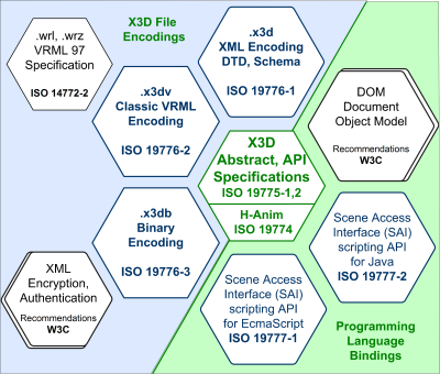
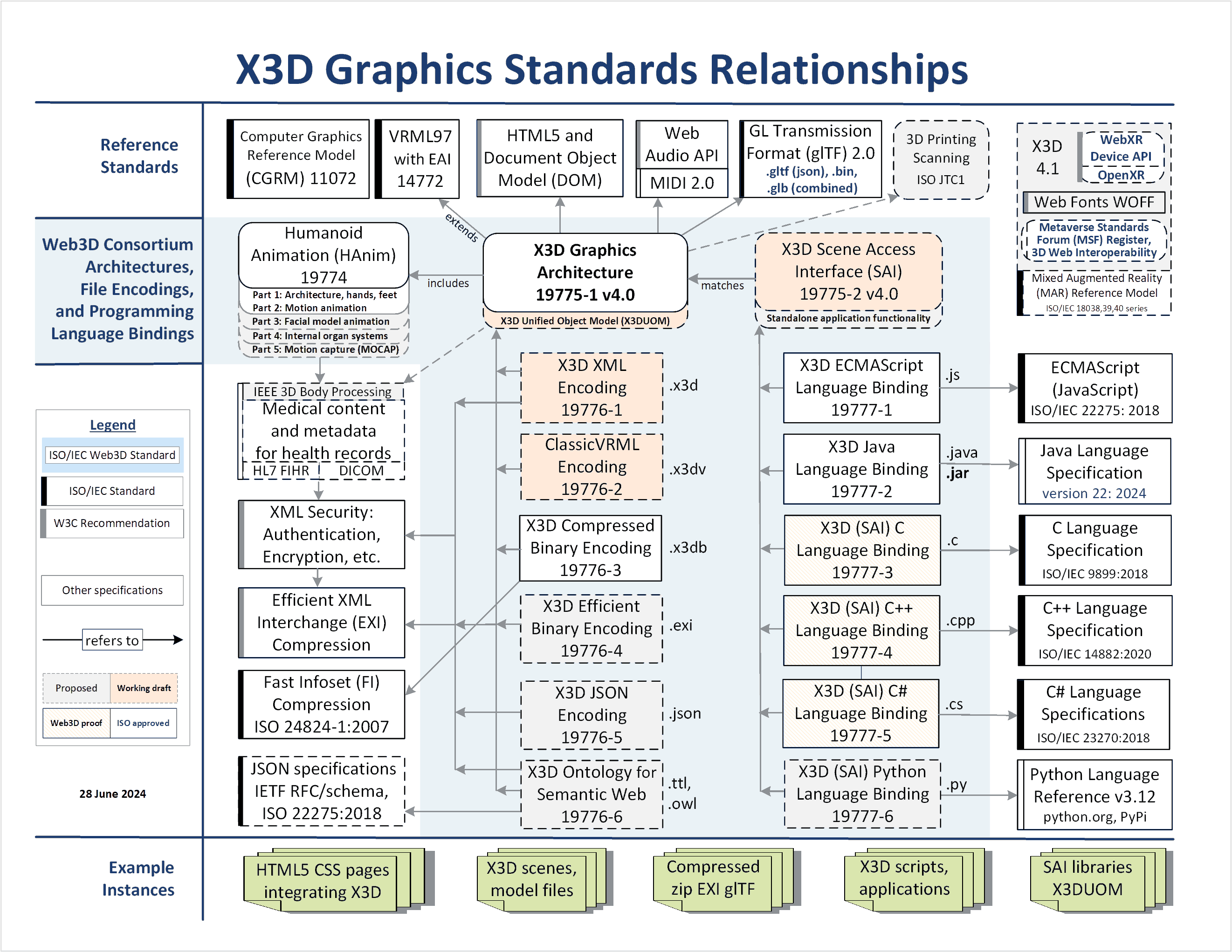
The X3D Graphics Standards Relationships diagram illustrates how these many specifications relate to each other. X3D is an ISO ratified, royalty-free open standards file format and run-time architecture to represent and communicate 3D scenes and objects. X3D graphics provides a system for the storage, retrieval and playback of real time graphics content embedded in applications, all within an open architecture to support a wide array of domains and user scenarios.
The Web3D Consortium Standards Strategy carefully improves and evolves our standards while maintaining long-term archival stability. These standards have been continuously developed, tested, maintained and updated by Web3D Consortium members for many years, starting with Virtual Reality Modeling Language (VRML) in 1997. Following public comment and subsequent approval by the Web3D Consortium, all changes are submitted to International Standards Organization (ISO) as part of a series of annual reviews by national bodies around the world. The X3D Working Group proceeds collaboratively at the best speed possible for achieving rigorous quality and stable evolution. Progress is supported by member and public contributions.
We welcome comments concerning any issue you might find in any specification. Each issue is promptly handled by the X3D Working Group with both email and teleconference review, and progress is tracked until each issue is resolved. Comments, bugs, or inconsistencies can be submitted on the Standards Comment Form where you have an opportunity to fully describe the issue. General comments or questions can be submitted on our Contact page. Thanks for your interest and all feedback.
| Number | Name | Version | Common Name | Status / Date | Link |
|---|---|---|---|---|---|
| 19774 | ISO/IEC IS 19774-1&2:2019 | V2.0 | Humanoid Animation (HAnim) : Architecture & Motion Data Animation |
IS 2019-11-11 |
HTML ZIP |
| 19774-1 | ISO/IEC IS 19774-1:2019 | V2.0 | Humanoid Animation (HAnim) : Architecture |
IS 2019-11-11 |
HTML ZIP |
| 19774-2 | ISO/IEC IS 19774-2:2019 | V2.0 | Humanoid Animation (HAnim) : Motion Data Animation |
IS 2019-11-11 |
HTML ZIP |
| 19775-1 | ISO/IEC IS 19775-1:2023 | V4.0 | X3D Abstract : Node Definitions |
IS 2023-12-12 |
HTML ZIP |
| 19775-2 | ISO/IEC 19775-2:2015 | V3.3 | X3D Abstract : Scene Access Interface (SAI) |
IS 2015-04-24 |
HTML ZIP |
| 19776-1 | ISO/IEC 19776-1:2015 | V3.3 | X3D Encoding : XML |
IS 2015-06-15 |
HTML ZIP |
| 19776-2 | ISO/IEC 19776-2:2015 | V3.3 | X3D Encoding : Classic VRML |
IS 2015-05-28 |
HTML ZIP |
| 19776-3 | ISO/IEC 19776-3:2015 | V3.3 | X3D Encoding : Compressed Binary |
IS 2015-05-28 |
HTML ZIP |
| 19777-1 | ISO/IEC CD 19777-1:201x | V3.3 | X3D Language Bindings : ECMAScript (JavaScript) |
CD 2014-09-05 |
HTML ZIP |
| 19777-2 | ISO/IEC IS 19777-2:2006 | V3.0 | X3D Language Bindings : Java |
IS 2006-05-15 |
HTML ZIP |
Naming Conventions
International Standards Organization (ISO) Standards and Revisions
| Acronym | Description | Meaning |
|---|---|---|
| CD | Committee Draft | First vote with technical comments on proposed standard or revision. |
| DIS (was FCD) | Draft International Standard (was Final Committee Draft) | Last vote with technical comments on proposed standard or revision. |
| FDIS | Final Draft International Standard | Last ISO vote on proposed standard or revision. This is a Yes/No vote only. |
| IS | International Standard | Approved and published standard or revision. |
International Standards Organization (ISO) Amendments
| Acronym | Description | Meaning |
|---|---|---|
| PDAM | Preliminary DRAFT Amendment | First vote with technical comments on an amendment. |
| FPDAM | Final Proposed Draft Amendment | Last ISO vote with technical comments on an amendment. |
| FDAM | Final Draft Amendment | Last ISO vote on amendment. This is a Yes/No vote only. |
| AM | Amendment | Approved and published amendment to a standard. |