Extensible 3D (X3D)
Part 1: Architecture and base components
43 Projective Texture Mapping Component
TODO: Mantis Issue 1255
The name of this component is "ProjectiveTextureMapping". This name shall be used when referring to this component in the COMPONENT statement (see 7.2.5.4 Component statement).
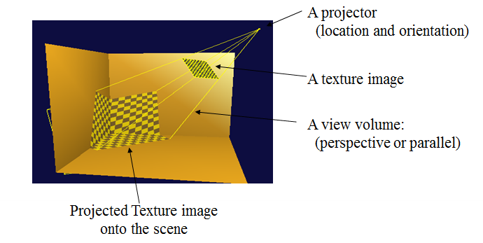
This component provides additional texturing extensions to the basic capabilities defined in X3D. Generally, 2D and 3D texture mapping (see Clauses 18 and 33) has been used to enhance the quality of an image generated with a camera or to speed up the generation of an image with respect to a given scene including several geometric models. However, there are some constraints for mapping region and shape of textures over objects. As an extension of texture mapping, the texture image can be projected onto a 3D scene within the projection volume which is constructed from projection parameters such as a projection point, a projection direction and a projection aspect ratio. Figire 1 shows an example screen shot by applying a projective texture mapping to a 3D virtual scene. The texture mapping of this type is called a projective texture mapping. .
This projective texture mapping is essential for enhanced rendering effects in a 3D scene such as rendering of beam projection images, visualization of a terrain surface in GIS applications, and medical visualization.
The projective texture mapping allows a texture image to be projected onto a 3D virtual scene inside the projection volume visible from a specific position called a projection point. The projection volume is determined by projection parameters depending on two types: parallel and perspective projections. In a parallel projection, the parallel volume will become a parallel volume and in a perspective projection, the projection volume will become the shape of the frustum.
The parallel projection can be distinguished into orthographic and oblique according to the defined projection direction. If all the projection lines are orthogonal to the projection plane, the projection is called orthographic projection. All the projection lines in oblique projection will intersect the projection plane at an oblique angle. In order to describe the types of parallel projection, the projection point and projection direction will be given as a point and a vector, respectively. The projection volume in parallel projection can be defined as a parallelepiped.
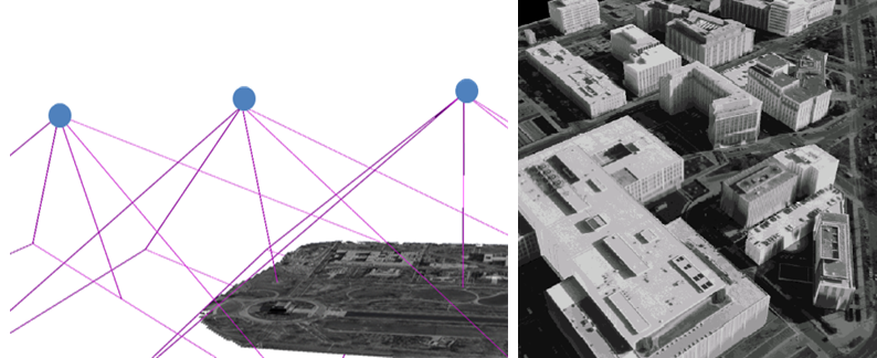
The perspective projection can be defined as a field of view angle from a projection point, an aspect ratio of width and height, near and far planes. In a projective texture mapping, generally, single texture as well as several texture images can be projected onto a scene in a 3D virtual world. Furthermore, multiple projective texture mapping can be performed over a common scene with specific objectives such as photogrammetry or reconstruction of endoscope images. As shown Figure 2, assume that several images are provided, each of which is taken with a different camera. Construction of a terrain surface from those images can be performed by displaying overlapping images obtained after applying several projective textures to the surface model.
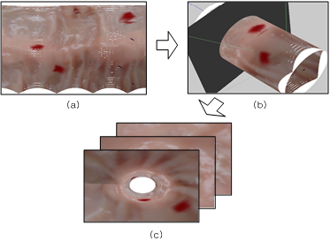
Figure 3 describes an example for reconstructing endoscope images over a cylinder by applying projective texture mapping. In a similar manner, each image is captured from an endoscope with perspective view information inside human body.
Node types specifying images for projective texture mapping may supply data with a number of color components between one and four. The valid types and interpretations of 3D textures are identical to that for 2D textures. The definition of texture formats is defined in 18.2.1 Texture map formats.
X3DTextureProjectorNode : X3DChildNode{
	SFNode		[in,out]	metadata	NULL	[X3DMetadataObject]
	SFString	[in,out]	description 	""
	SFVec3f		[in,out]	location	0 0 0 (-∞,∞)
	SFVec3f		[in,out]	direction	0 0 1 (-∞,∞)
	SFFloat		[out]		aspectRatio
	SFFloat		[in,out]	nearDistance    1
     	SFFloat		[in,out] 	farDistance     10
	SFBool      	[in,out]	global		true
     	SFBool     	[in,out]	on		true
	SFNode 		[in,out] 	texture 	NULL
					[X3DTexture2DNode]
}
This abstract node type is the base type for all node types that specify projective texture mapping.
The description field of this node tells the name of the projector, and makes the division of different projectors possible.
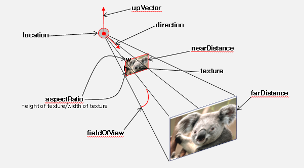
The location shows the position of the projector, and this implies projection point.
The direction is the way the projector is heading, and this implies to projection direction.
The aspectRatio is the aspect ratio of the width and length which refers to projection spect ratio.
The nearDistance and farDistance is the minimum and maximum distance that is shown on the screen, respectively.
We could draw out projection volume and projection texture coordinate from the added fields.
Each projective texture mapping type defines a global field that determines whether the projective texture mapping is global or scoped. Global projective texture mapping performs the texture mappings for all objects that fall within their volume of projective texture mapping influence. Scoped projective texture mapping only performs the texture mappings for objects that are in the same transformation hierarchy as the projective texture mapping; i.e., only the children and descendants of its enclosing parent group are illuminated.
The on field specifies whether the projective texture mapping is performed or not. If on is TRUE, the projective texture mapping is performed for geometry objects in the scene. If on is FALSE, the projective texture mapping is not performed for any geometry in the scene.
See 18 Texturing component for a general description of the X3DTexture2DNode abstract type and interpretation of rendering for 2D images.
TextureProjectorPerspective : X3DTextureProjectorNode {
	SFNode	 [in,out]	metadata	NULL 	[X3DMetadataObject]
	SFString [in,out]	description 	""
	SFVec3f	 [in,out]	location	0 0 1
	SFvec3f	 [in,out]	direction	0 0 1
	SFFloat	 [in,out]	fieldOfView 	π/4 (0,π)
	SFFloat	 [out]		aspectRatio
	SFVec3f	 [in,out]	upVector	0 0 1
	SFFloat	 [in,out]	nearDistance    1
        SFFloat	 [in,out] 	farDistance     10
	SFBool	 [in,out] 	global		true
        SFBool	 [in,out] 	on		true
 	SFNode 	 [in,out] 	texture 	NULL
				[X3DTexture2DNode]
}
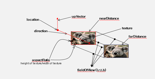
Perspective texture mapping is shown in the following figure.
The description field of this node tells the name of the persepective projector, and makes the division of different perspective projectors possible.
The location shows the position of the perspective projector, and this implies perspective projection point.
The direction is the way the perspective projector is heading, and this implies to perspective projection direction.
The fieldOfView is the extent of the observable world that is perspectively seen on the display at any given moment. This value may change depending on the aspect ratio of the rendering resolution. The default value of this field is π/4.
The aspectRatio is the aspect ratio of the width and length which refers to perspective projection spect ratio.
The upVector describes the roll of the camera by saying which point is "up" in the camera's orientation. The default value of this field is (0 0 1).
The nearDistance and farDistance is the minimum and maximum distance that is shown on the screen, respectively.
global, on and texture fields are the same as illustrated in the Abstract node.
TextureProjectorParallel : X3DTextureProjectorNode{
	SFNode	 [in,out]	metadata	NULL [X3DMetadataObject]
	SFString [in,out]	description 	""
	SFVec3f	 [in,out]	location	0 0 1
	SFVec3f	 [in,out]	direction 	0 0 1
	SFFloat	 [out]		aspectRatio
	MFFloat	 [in,out]  	fieldOfView	-1 -1 1 1 (-∞,∞)
       	SFFloat	 [in,out] 	nearDistance    1
       	SFFloat	 [in,out] 	farDistance     10
       	SFBool	 [in,out] 	global		true
       	SFBool	 [in,out] 	on		true
       	SFNode 	 [in,out] 	texture 	NULL
				[X3DTexture2DNode]
}
Parallel texture mapping is shown in the following figure.
The description field of this node tells the name of the persepective projector, and makes the division of different perspective projectors possible.
The location shows the position of the perspective projector, and this implies perspective projection point.
The direction is the way the perspective projector is heading, and this implies to perspective projection direction.
The fieldOfView is the extent of the observable world that is parallely seen on the display at any given moment. This value may change depending on the aspect ratio of the rendering resolution. The default value of this field is (-1 -1 1 1).
The aspectRatio is the aspect ratio of the width and length which refers to perspective projection spect ratio.
The nearDistance and farDistance is the minimum and maximum distance that is shown on the screen, respectively.
global, on and texture fields are the same as illustrated in the Abstract node.
TODO: convert to ClassicVRML syntax
<X3D profile="Interactive" version="3.3">
<Scene>

<TextureProjectorPerspective
	description='pt1' location='3 3 3' direction='-1 0 -1'
    	fieldOfView=‘0.26' nearDistance='1' farDistance='10'
	upVector='0 1 0' global= 'true' on= 'true'>

	<ImageTexture url='C:/image/apple.jpg' repeatS='false' repeatT='false'/>
</TextureProjectorPerspective>

<Shape>
    <Appearance>
	<Material diffuseColor='0.5 0.5 0.5'/>
    </Appearance>

    <IndexedFaceSet solid='false' coordIndex="3 2 1 0 -1, 4 5 2 3-1, 5 6 1 2 -1">
    <Coordinate point="1 0 1, -1 0 1, -1 0 -1, 1 0 -1, 1 1 -1, -1 1 -1, -1 1 1 "/>
    </IndexedFaceSet>
</Shape>
</Scene>
</X3D>
The projective texture mapping component defines levels of support as specified in Table 43.2.
Table 43.2 — Projective texture mapping component support levels
| Level | Prerequisites | Nodes/Features | Support |
|---|---|---|---|
| 1 | Core 1 Grouping 1 Shape 1 Rendering 1 Texturing 1 |
||
| X3DTextureProjectorNode | n/a | ||
| TextureProjectorPerspective | All fields fully supported. | ||
| 2 | Core 1 Grouping 1 Shape 1 Rendering 1 Texturing 1 |
||
| TextureProjectorParallel | All fields fully supported. |