Extensible 3D (X3D)
Part 1: Architecture and base components
33 Texturing3D Component
The name of this component is "Texturing3D". This name shall be used when referring to this component in the COMPONENT statement (see 7.2.5.4 Component statement).
This component provides additional texturing extensions to the basic capabilities defined in X3D. Many applications need to describe surface properties as data points in a volume of space, rather than a flat surface. These textures operate with three dimensions. A texture of this type is termed a volumetric texture.
Volumetric textures are essential for advanced rendering effects related to fog and lighting, as well as industry-specific needs such as medical and CAD visualization.
3D texturing specifies texel colours based on a volume of space. An object that is being rendered on that 3D texture effectively cuts a volume out of the texels provided by the texture.
This part of ISO/IEC 19775 assumes standard commodity hardware that presents 3D textures as a series of 2D slices of the volume that can then be interpolated and composited together to form a 3D volume of space. There is no assumption about the existence of true voxel rendering hardware capability.
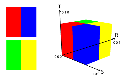
A 3D volume of texture is specified as a number of 2D planes (images) of data that are ordered in a depth-wise manner. Figure 33.1 shows two base images that can be layered together resulting in the volume of a 3D texture. In this example, the texture would have a dimension of n × m × 2.
The coordinate system of the texture is a right-handed coordinate system as defined in Figure 33.1. The coordinate components are defined to be (s,t,r) as values along the S, T, and R axes defined by Figure 33.1.
Some geometry nodes are not capable of having 3D texture coordinates set by the user (e.g., Box and Cone). For these cases, 3D textures coordinates are automatically generated based on the following rules:
Node types specifying 3D texture maps may supply data with a number of color components between one and four. The valid types and interpretations of 3D textures are identical to that for 2D textures. The definition of texture formats is defined in 18.2.1 Texture map formats.
X3DTexture3DNode : X3DTextureNode {
  SFNode [in,out] metadata          NULL  [X3DMetadataObject]
  SFBool []       repeatS           FALSE
  SFBool []       repeatT           FALSE
  SFBool []       repeatR           FALSE
  SFNode []       textureProperties NULL  [TextureProperties]
}
This abstract node type is the base type for all node types that specify 3D sources for texture images.
NOTE The base node type diverges from the standard X3D textures by making the default repeat modes FALSE, rather that TRUE. This is because 3D textures are almost never used in a repeated rendering mode, and because repeat mode TRUE for 3D textures can produce odd rendering artifacts.
ComposedTexture3D : X3DTexture3DNode {
  SFNode [in,out] metadata          NULL  [X3DMetadataObject]
  MFNode [in,out] texture           []    [X3DTexture2DNode]
  SFNode []       textureProperties NULL  [TextureProperties]
  SFBool []       repeatS           FALSE
  SFBool []       repeatR           FALSE
  SFBool []       repeatT           FALSE
}
The ComposedTexture3D node defines a 3D image-based texture map as a collection of 2D texture sources at various depths and parameters controlling tiling repetition of the texture onto geometry.
The texture values are interpreted with the first image being at depth 0 and each following image representing an increasing depth value in the R direction. A user shall provide 2n source textures in this array. The individual source textures will ignore their repeat field values.
See 33.2 Concepts, for a general description of texture maps.
See 18 Texturing component for a general description of the X3DTexture2DNode abstract type and interpretation of rendering for 2D images. When used as a source for cubic environment maps, the fields repeatS and repeatT fields shall be ignored.
ImageTexture3D : X3DTexture3DNode, X3DUrlObject {
  SFNode   [in,out] metadata          NULL  [X3DMetadataObject]
  MFString [in,out] url               []    [URI]
  SFBool   []       repeatS           FALSE
  SFBool   []       repeatT           FALSE
  SFBool   []       repeatR           FALSE
  SFNode   []       textureProperties NULL  [TextureProperties]
}
The ImageTexture3D node defines a texture map by specifying a single image file that contains complete 3D data and general parameters for mapping texels to geometry.
The texture is read from the URL specified by the url field. When the url field contains no values ([]), texturing is disabled. The url field is defined in 9.2.1 URLs. While there are no required file formats, it is recommended that one of the following formats be supported:
See 33.2 Concepts for a general description of texture maps.
PixelTexture3D : X3DTexture3DNode {
  SFNode  [in,out] metadata          NULL      [X3DMetadataObject]
  MFInt32 [in,out] image             [0 0 0 0]
  SFBool  []       repeatS           FALSE
  SFBool  []       repeatR           FALSE
  SFBool  []       repeatT           FALSE
  SFNode  []       textureProperties NULL      [TextureProperties]
}
The PixelTexture3D node defines a 3D image-based texture map as an explicit array of pixel values (image field) and parameters controlling tiling repetition of the texture onto geometry.
The image field describes the raw data to be used for this 3D texture. The first value of the array is the number of components to the image and shall be a value between 0 and 4. The following three numbers are the size of the texture: width, height and depth, respectively. The remaining values of the array are treated as the pixels for the image. There shall be at least width × height × depth number of pixel values provided. Each of the width, height and depth values is required to be a power of two.
See 33.2 Concepts for a general description of 3D texture maps.
See 17 Lighting component for a description of how the texture values interact with the appearance of the geometry. 5.7 SFImage and MFImage describes the specification of an image.
TextureCoordinate3D : X3DTextureCoordinateNode {
  SFNode  [in,out] metadata NULL [X3DMetadataObject]
  MFVec3f [in,out] point    []   (-∞,∞)
}
The TextureCoordinate3D node is a geometry property node that specifies a set of 3D texture coordinates used by vertex-based geometry nodes (e.g., IndexedFaceSet and ElevationGrid) to map 3D textures to vertices.
Providing 3D texture coordinates to objects that only have 2D textures defined shall result in implementation dependent rendering.
TextureCoordinate4D : X3DTextureCoordinateNode {
  SFNode  [in,out] metadata NULL [X3DMetadataObject]
  MFVec4f [in,out] point    []   (-∞,∞)
}
The TextureCoordinate4D node is a geometry property node that specifies a set of 4D (homogeneous 3D) texture coordinates used by vertex-based geometry nodes (e.g., IndexedFaceSet and ElevationGrid) to map 3D textures to vertices.
Providing 4D texture coordinates to objects that only have 2D textures defined shall result in implementation dependent rendering.
TextureTransformMatrix3D : X3DTextureTransformNode {
  SFNode     [in,out] metadata    NULL    [X3DMetadataObject]
  SFMatrix4f [in,out] matrix      1 0 0 0 0 1 0 0 0 0 1 0 0 0 0 1  (-∞,∞)
}
The matrix field specifies a generalized, unfiltered 4×4 transformation matrix that can be used to modify the texture. Any set of values is permitted.
TextureTransform3D : X3DTextureTransformNode {
  SFVec3f    [in,out] center      0 0 0   (-∞,∞)
  SFNode     [in,out] metadata    NULL    [X3DMetadataObject]
  SFRotation [in,out] rotation    0 0 1 0 (-∞,∞)
  SFVec3f    [in,out] scale       1 1 1   (-∞,∞)
  SFVec3f    [in,out] translation 0 0 0   (-∞,∞)
}
The TextureTransform3D node specifies a 3D transformation that is applied to texture coordinates (see 33.4.4 TextureCoordinate3D). This node affects the way texture coordinates are applied to the geometric surface. The transformation consists of (in order):
These parameters support changes to the size, orientation, and position of textures on shapes. These operations appear reversed when viewed on the surface of geometry.
EXAMPLE A scale value of (1 2 2) will scale the texture coordinates and have the net effect of shrinking the texture size by a factor of 2 (texture coordinates are twice as large and thus cause the texture to repeat) in the T and R dimensions and leave the S dimension unscaled. A translation of (0.5 0.0 0.0) translates the texture coordinates +0.5 units along the S-axis and has the net effect of translating the texture -0.5 along the S-axis on the geometry's surface. A rotation of π/2 of the texture coordinates results in a -π/2 rotation of the texture on the geometry.
The center field specifies a translation offset in texture coordinate space about which the rotation and scale fields are applied. The scale field specifies a scaling factor in S, T and R of the texture coordinates about the center point. All scale values shall be in the range (-∞,∞). The rotation field specifies a rotation of the texture coordinates about the center point after the scale has been applied. A positive rotation value makes the texture coordinates rotate counterclockwise about the centre, thereby rotating the appearance of the texture itself clockwise. The translation field specifies a translation of the texture coordinates.
A 3D transform may be applied to 2D textures. The results are implementation dependent.
The 3D Texturing component defines two levels of support as specified in Table 33.2.
Table 33.2 — 3D texturing component support levels
| Level | Prerequisites | Nodes/Features | Support |
|---|---|---|---|
| 1 | Core 1 Grouping 1 Shape 1 Rendering 1 Texturing 1 |
||
| X3DTexture3DNode | n/a | ||
| TextureMatrixTransform | All fields fully supported. | ||
| TextureTransform3D | All fields fully supported. | ||
| TextureCoordinate3D | All fields fully supported. | ||
| TextureCoordinate4D | All fields fully supported. | ||
| ComposedTexture3D | All fields fully supported. | ||
| PixelTexture3D | All fields fully supported. | ||
| 2 | Core 1 Grouping 1 Shape 1 Rendering 1 Texturing 1 |
||
| ImageTexture3D | All fields fully supported. |